Southern New Hampshire University | SNHU-CYB220: Network Security
Implement the Cisco Adaptive Security Appliance
Exercises
- Introduction
- Exercise 1 - Configuring Core ASA Features
- Exercise 2 - Configuring NAT
- Exercise 3 - Configuring a Security Policy
- Exercise 4 - Modular Policy Framework
- Summary
Introduction
The Implement the Cisco Adaptive Security Appliance module provides you with the instructions and Cisco hardware to develop your hands-on skills in the following topics:
- Configuring core ASA features
- Configuring NAT
- Configuring a security policy
- Modular Policy Framework
Exam Objectives
The following exam objectives are covered in this lab:
- CS0-001 1.3: Given a network-based threat, implement or recommend the appropriate response and countermeasure.
- CS0-001 2.1: Given a scenario, implement an information security vulnerability management process.
- CS0-001 4.1: Explain the relationship between frameworks, common policies, controls, and procedures.
- CS0-001 4.2: Given a scenario, use data to recommend remediation of security issues related to identity and access management.
- CS0-001 4.3: Given a scenario, review security architecture and make recommendations to implement compensating controls.
- CS0-001 4.5: Compare and contrast the general purpose and reasons for using various cybersecurity tools and technologies.
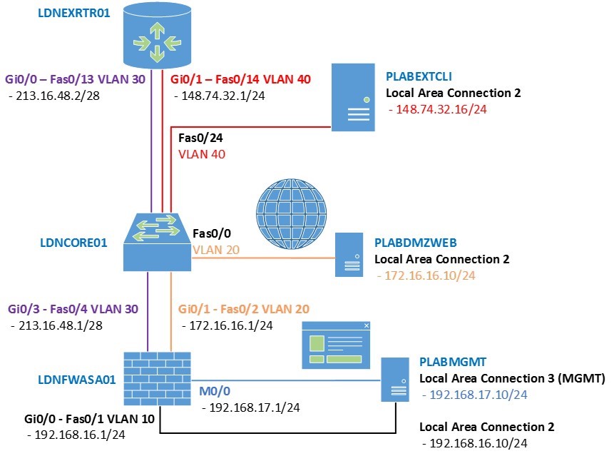
Lab Diagram
During your session, you will have access to the following lab configuration. Depending on the exercises you may or may not use all of the devices, but they are shown here in the layout to get an overall understanding of the topology of the lab.
Connecting to your Lab
In this module, you will be working on the following equipment to carry out the steps defined in each exercise.
- LDNFWASA01 (Cisco ASA Firewall)
- LDNCORE1 (Cisco Switch)
- LDNEXTRTR01 (Cisco Router)
- PLABMGMT (Windows Management Station)
- PLABDMZWEB (Windows Server 2008 R2 - Web Server)
- PLABEXTCLI (Windows Server 2008 R2 - Web Server)
To start, simply choose a device and click Power on. In some cases, the devices may power on automatically.
For further information and technical support, please see our Help and Support page.
Copyright Notice
This document and its content is copyright of Practice-IT - © Practice-IT 2017. All rights reserved. Any redistribution or reproduction of part or all of the contents in any form is prohibited other than the following:
1. You may print or download to a local hard disk extracts for your personal and non-commercial use only.
2. You may copy the content to individual third parties for their personal use, but only if you acknowledge the website as the source of the material. You may not, except with our express written permission, distribute or commercially exploit the content. Nor may you transmit it or store it in any other website or other form of electronic retrieval system.
Exercise 1 - Configuring Core ASA Features
In this module you will configure a Cisco ASA firewall, enabling Internet access for the internal users and DMZ web access for external Internet-based users to be able to access your corporate web server.
If you look at the diagram, your internal host is PLABMGMT. This will act as your management station and an internal test client. PLABDMZWEB is the web server that should be accessible from the outside world. PLABEXTCLI will as two things: firstly, it will be a client machine that will be used to test access to the corporate web server and secondly it will be used as a test web server that your internal management station will be able to browse to. Both PLABDMZWEB and PLABEXTCLI are running Microsoft IIS server, a web server, with a test website.
In this exercise, you will build the base configuration of the Cisco ASA firewall, LDNFWASA01 so that you can remotely connect and use the Cisco ASA Device Manager (ASDM) to make further configuration changes to the firewall.
To enable remote access to the ASA firewall, you need to have the following configured:
- An IP address either on an internal interface on the firewall, or the management interface (which you will use)
- The HTTP server enabled on the firewall
- An access list enabling remote access to the device
- A username and password to authenticate with
If you observe the diagram, you will also need to configure the IP addresses on the ASA interfaces enabling IP connectivity throughout the lab. The switch and external router have been pre-configured to make life a little easier. You will configure the ASA interfaces in the next steps using the ASDM software, but to connect using the ASDM you need some base configuration on the ASA.
Important: If you are connecting with a screen resolution less than 1024 * 768 you may find the dialog is cut off. You will need to reconnect with at least this resolution (the screenshots taken here have a resolution of 1024 * 768).
Task 1 - Configure ASA Firewall
Before starting this task, please ensure that you have powered on the required devices indicated in the Introduction of this exercise.
Step 1
Click LDNFWASA01 firewall device. Wait for a few moments while the firewall is being initialized.
In this task, you will configure an IP address and a name for the Management 0/0 interface on the LDNFWASA01 firewall. You will also configure a hostname so that you know which device you are on.
On the LDNFWASA01 device, when the Pre-configuration prompt appears, type no.
You will then be redirected to the ciscoasa> prompt. Type enable. There is no password so simply press Enter to get access to privileged mode.
Pre-configure Firewall now through interactive prompts [yes]? no
Type help or '?' for a list of available commands.
ciscoasa>
ciscoasa>
ciscoasa> enable
Password:
ciscoasa#
Type configure terminal to gain access to the global configuration mode. You will notice that in new versions of the ASA software you are prompted to say whether or not you want the ASA to call home if there is an error (i.e. communicate with Cisco). Because you do not require this, and because of the fact that this ASA is not actually connected to the Internet, you can answer no to this question:
ciscoasa(config)#
***************************** NOTICE *****************************
Help to improve the ASA platform by enabling anonymous reporting,
which allows Cisco to securely receive minimal error and health
information from the device. To learn more about this feature,
please visit: http://www.cisco.com/go/smartcall
Would you like to enable anonymous error reporting to help improve
the product? [Y]es, [N]o, [A]sk later: n
In the future, if you would like to enable this feature,
issue the command "call-home reporting anonymous".
Please remember to save your configuration.
ciscoasa(config)#
Continue the configuration by defining a hostname and configuring an IP address on the Management 0/0 interface like so:
ciscoasa(config)#hostname LDNFWASA01
LDNFWASA01(config)#interface management 0/0
LDNFWASA01(config-if)#nameif management
INFO: Security level for "management" set to 0 by default.
LDNFWASA01(config-if)#ip address 192.168.17.1 255.255.255.0
LDNFWASA01(config-if)#no shutdown
LDNFWASA01(config-if)#exit
LDNFWASA01(config)#
Notice that the security level for management was automatically set to 0.
Step 2
In order for you to gain some CLI experience, you will also configure the internal interface via the command line. Configure the GigabitEthernet0/0 interface with a name and an IP address:
LDNFWASA01#configure terminal
LDNFWASA01(config)#interface gigabitethernet 0/0
LDNFWASA01(config-if)#nameif inside
INFO: Security level for "inside" set to 100 by default.
LDNFWASA01(config-if)#ip address 192.168.16.1 255.255.255.0
LDNFWASA01(config-if)#no shutdown
LDNFWASA01(config-if)#exit
LDNFWASA01(config)#
Step 3
Next, you must enable the HTTP server, and allow the management station PLABMGMT with an IP address of 192.168.17.10 to access to the device:
LDNFWASA01(config)#http server enable
LDNFWASA01(config)#http 192.168.17.10 255.255.255.255 management
LDNFWASA01(config)#management-access management
LDNFWASA01(config)#
Step 4
Finally, you must add a user to authenticate to the ASA. Ensure you use exactly this username and password combination so you can recover the device successfully:
LDNFWASA01(config)#username cisco password cisco
LDNFWASA01(config)#
Task 2 - Configuring the ASA interfaces using the ASDM software
Now you have configured remote access for the ASDM. Note that SSH access has not yet been configured. You can use PLABMGMT to connect to the ASA for GUI-based access.
Ensure PLABMGMT, PLABDMZWEB, and PLABEXTCLI are all powered on.
Step 1
Connect to the desktop of PLABMGMT. You will notice there is an icon for the Cisco ASDM-IDM Launcher on the desktop. Double-click this icon to launch the ASDM software.
Once open, you will see a login prompt. Ensure that the Device IP Address / Name is set to 192.168.17.1, that the username is cisco and the password is cisco, and that Run in Demo Mode is unchecked (you are connecting to a real Cisco ASA), then click OK.
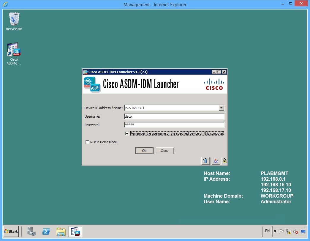 Figure 1.1 Cisco ASDM: The launch screen of the Cisco ASDM software
Step 2
The first time you connect, you may get a security prompt asking if you trust this publisher. Check the checkbox and click Yes:
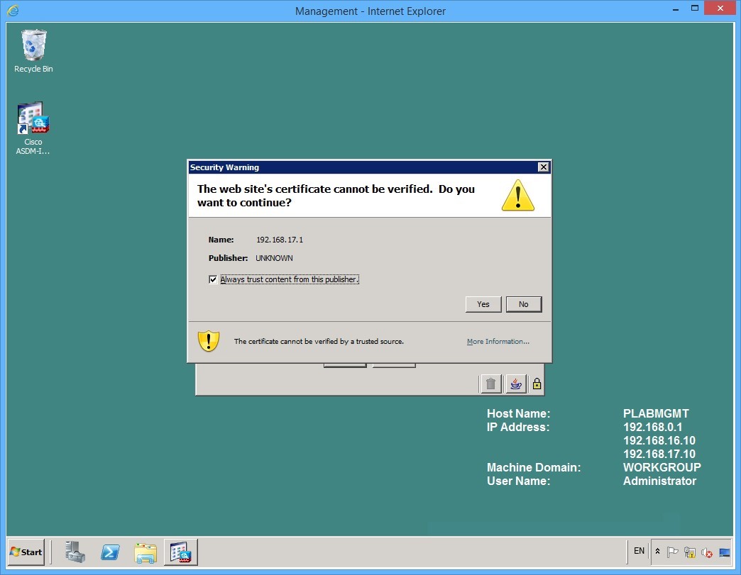 Figure 1.2 Cisco ASDM: A security warning may appear the first time the software is launched
Step 3
Once the software has loaded, you will see a device dashboard showing the license information, the software versions, the memory status, the device uptime and some graphs that are ticking.
You must configure the interfaces so that you can build a firewall policy.
Notice that at the bottom of the ASDM window you can see that there are no log entries, and there is a button labelled Enable Logging to turn on the logging to the ASDM. Click this button so you can see log entries on the dashboard.
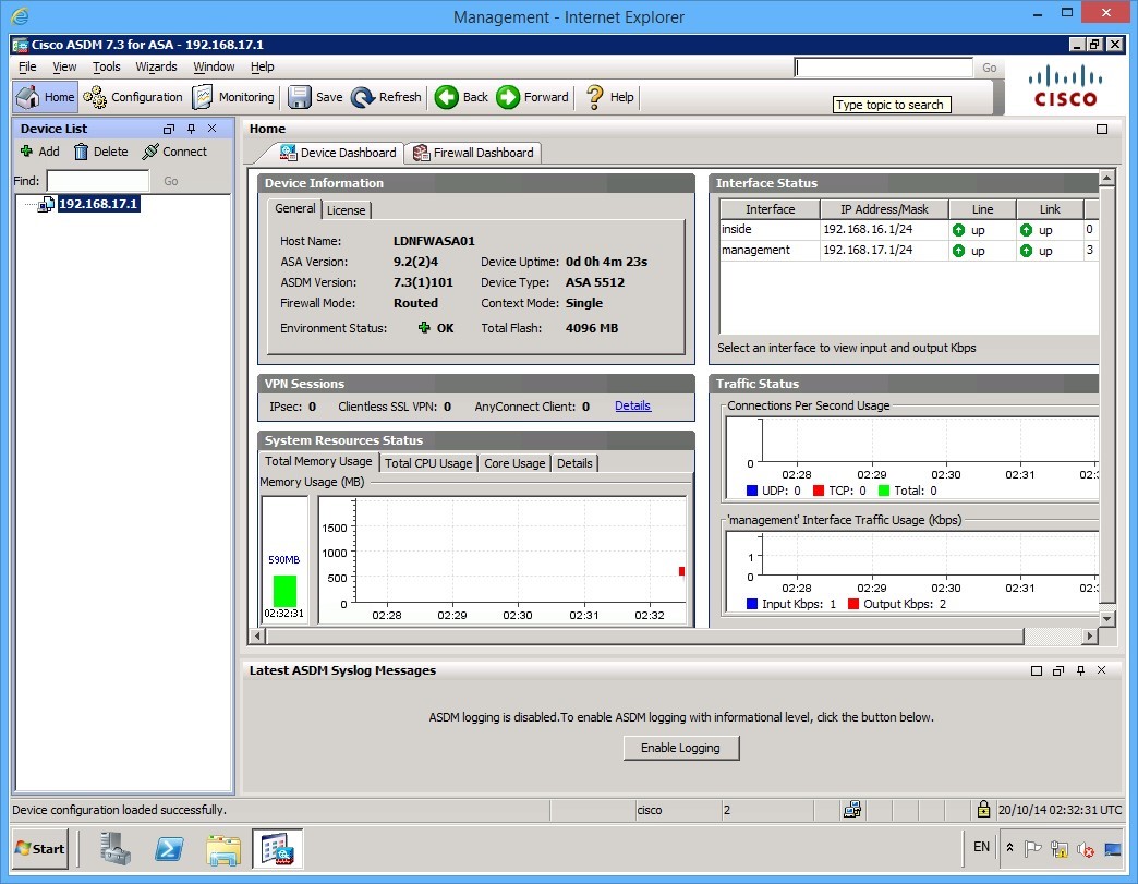 Figure 1.3 Cisco ASDM: The Enable Logging button is near the bottom of the ASDM window
Step 4
If the device list appears to the left, you can close this by clicking the X at the top of the panel. It is easier to see everything without the device list, however, in the real world you may be configuring multiple ASAs and then the device list becomes useful.
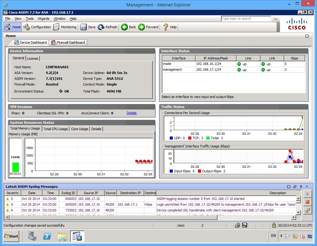 Figure 1.4 Cisco ASDM: The ASDM window after the device list panel is closed.
Step 5
To configure interfaces, you must be in configuration mode. Click the Configuration icon at the top left of the ASDM screen:
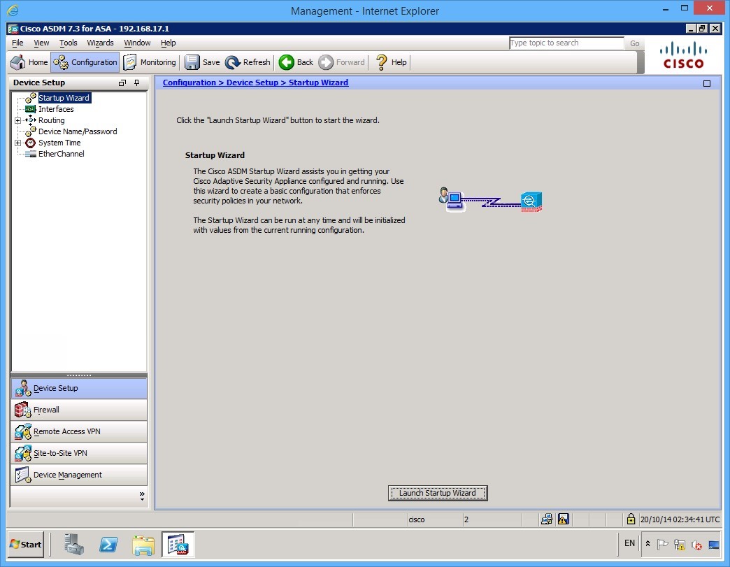 Figure 1.5 Cisco ASDM: The ASDM window after clicking the Configuration toolbar button
Step 6
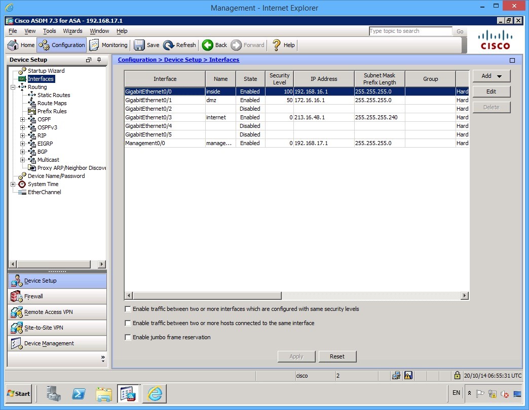
In the device setup panel on the left, click Interfaces. You will see that your configuration on the GigabitEthernet0/0 and Management 0/0 interfaces is populated with the configuration that you applied using the CLI in Task 1.
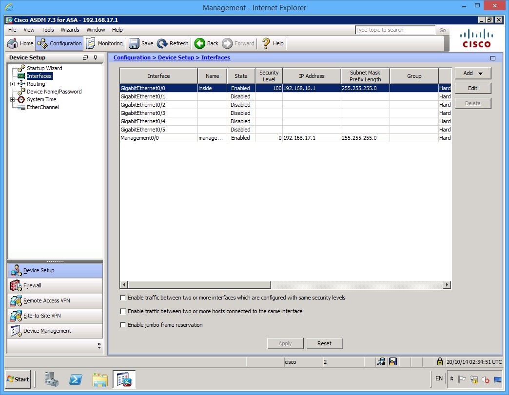 Figure 1.6 Cisco ASDM: The interface list shows the results if the configuration that was applied using the CLI in Task 1.
Step 7
Refer back to the Lab Diagram in the Introduction for reference. You will configure the network interfaces using the following settings:
GigabitEthernet 0/1 (This is the DMZ interface)
- IP Address: 172.16.16.1 /24
- Name: dmz
- Security Level: 50
GigabitEthernet 0/3 (This is the Internet facing interface)
- IP Address: 213.16.48.1 /28
- Name: internet
- Security Level: 0
To configure the DMZ interface, double click the GigabitEthernet0/1 interface in the middle pane.
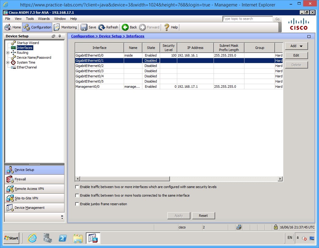 Figure 1.7 Cisco ASDM: To configure the GigabitEthernet 0/1 interface, double click on the interface in the list
Step 8
The Edit Interface dialog box appears with the interface configuration. Enter the following parameters:
- Interface Name: dmz
- Security Level: 50
- Enable Interface: checked
- IP address: 172.16.16.1
- Subnet mask 255.255.255.0
You may also include a Description as shown, however, this is optional.
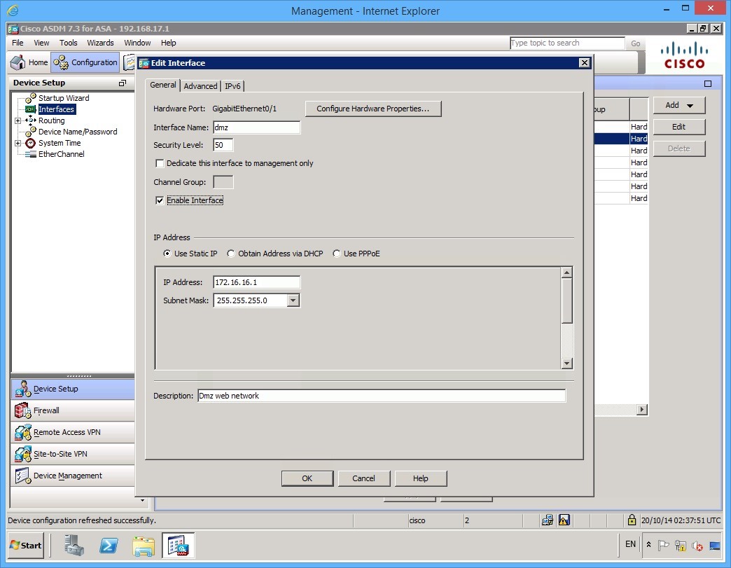 Figure 1.8 Cisco ASDM: Complete the parameter fields to configure the GigabitEthernet 0/1 interface correctly.
Step 9
If you click on the Advanced tab, you will notice that a Security Level Change warning appears. It is safe to click OK at this point, however, in a production network, be careful when changing security levels.
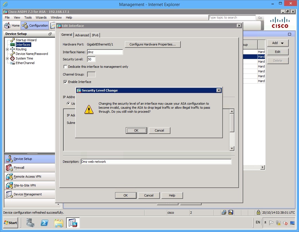 Figure 1.8 Cisco ASDM: A Security Level Change warning appears when you navigate away from the Edit Interface dialog box
Step 10
Note the settings on the Advanced tab for reference. You don’t need to change these. Take a look at the settings on the IPv6 tab as well.
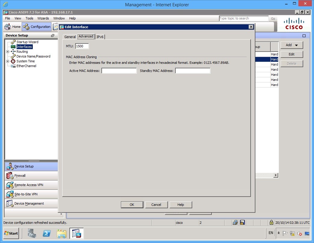 Figure 1.9 Cisco ASDM: The settings on the Advanced tab of the Edit Interface dialog box
Step 11
Click OK to accept the configuration. At this point, the configuration has not been applied to the ASA. Notice that at the bottom of the ASDM window an Apply button is no longer greyed out:
 Figure 1.10 Cisco ASDM: After making changes to the Edit Interface dialog box, the Apply button is no longer greyed out
Step 12
Before clicking apply, double-click the GigabitEthernet0/3 interface. Configure GigabitEthernet0/3 with the following settings:
- Interface Name: internet
- Security Level: 0
- Select Enable Interface check box
- IP Address: 213.16.48.1
- Subnet Mask: 255.255.255.240
Again, including a Description is optional. Click OK once you have configured the interface.
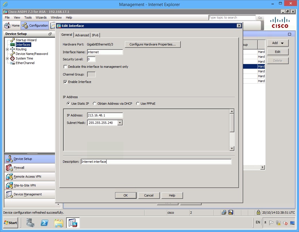 Figure 1.11 Cisco ASDM: The completed parameters of the GigabitEthernet 0/3 interface
Step 13
Click OK once again when presented with the Security Level Change dialog box.
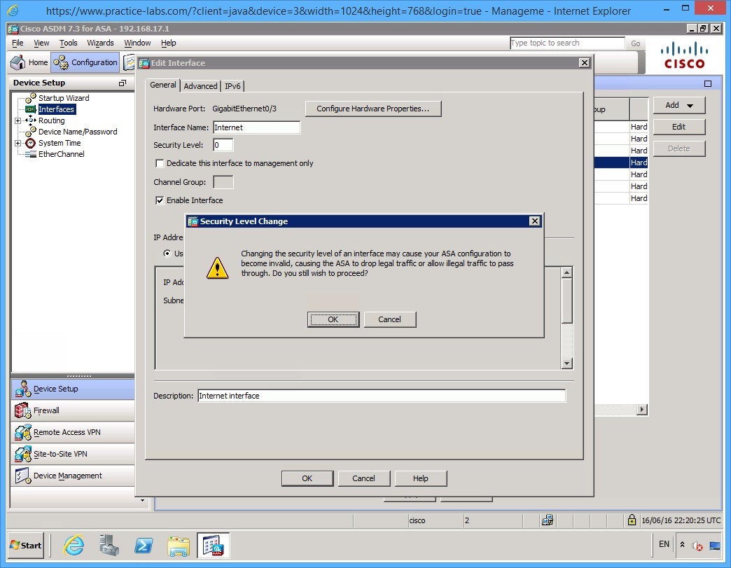 Figure 1.12 Cisco ASDM: A Security Level Change warning appears when you accept the changes made to the interface
Step 14
With both interfaces now configured, click the Apply button. Wait while the new settings are being applied and saved.
The ASDM software sends the relevant commands to the ASA. Once complete, the Please wait… status window disappears, and the Apply button becomes greyed out once more.
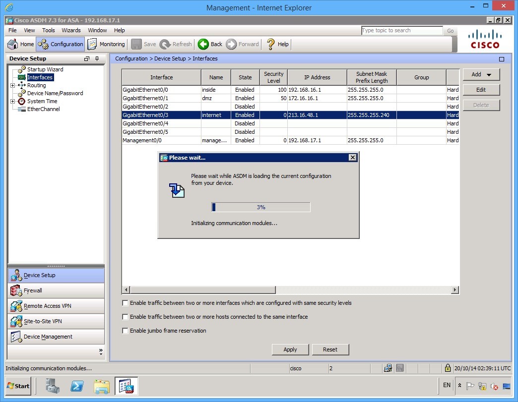 Figure 1.13 Cisco ASDM: The Please wait… status window appears as the configuration changes are being applied.
Step 15
Before configuring the security policy, the final thing to do is to configure routing. In this example, you only need to add a default outbound route. The next hop will be the GigabitEthernet 0/0 interface on the LDNEXTRTR01 router.
To do this, expand the Routing item in the Device setup panel on the left and then click Static Routes.
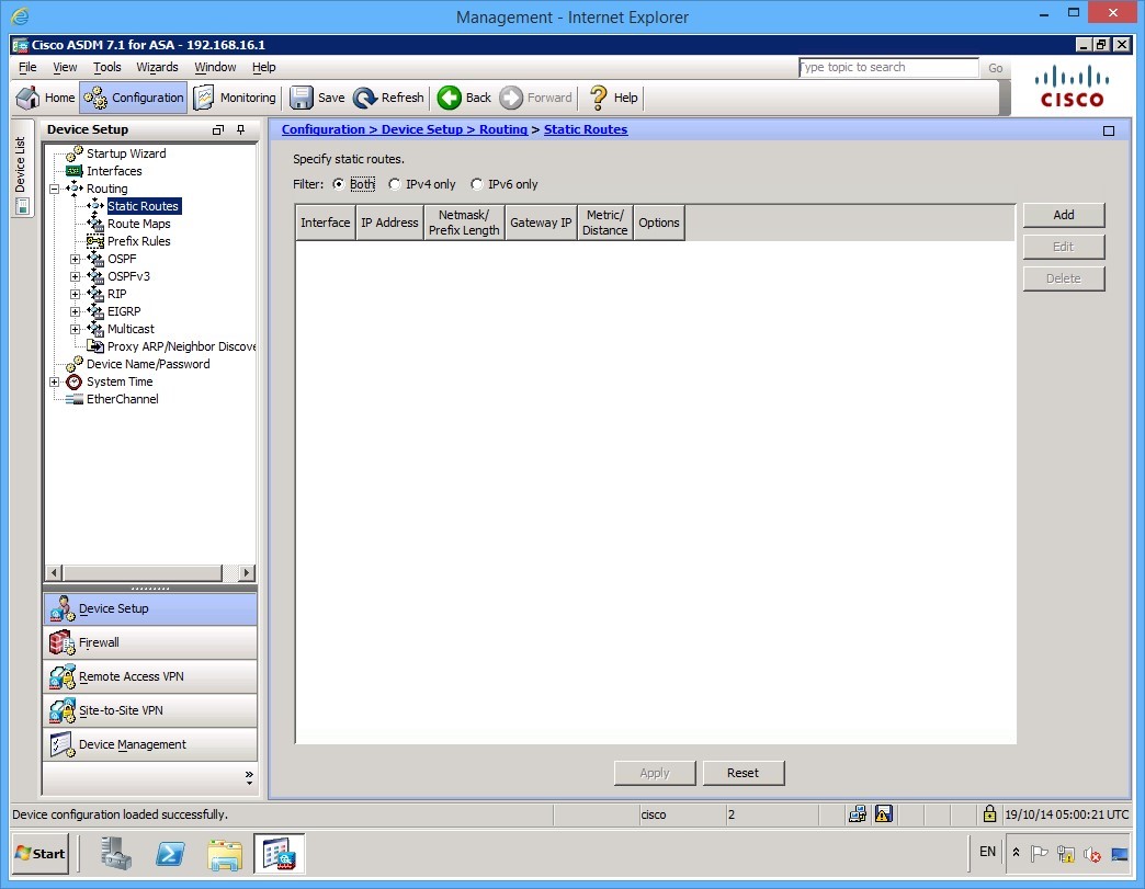 Figure 1.14 Cisco ASDM: The Static Routes list on the ASA.
Step 16
Click the Add button on the right. On the Add Static Route dialog box, make the following changes:
- Interface: internet
- Network: 0.0.0.0/0
- Gateway IP: 213.16.48.2
- Metric: 1
Note: Notice the /0 at the end of the Network setting. This is equivalent to 0.0.0.0 with a subnet mask of 0.0.0.0 mask. In other words, this means “anything.” Alternatively, you can use the keyword any in this field.
Leave the options settings as they are. Once you have completed your route configuration, click OK.
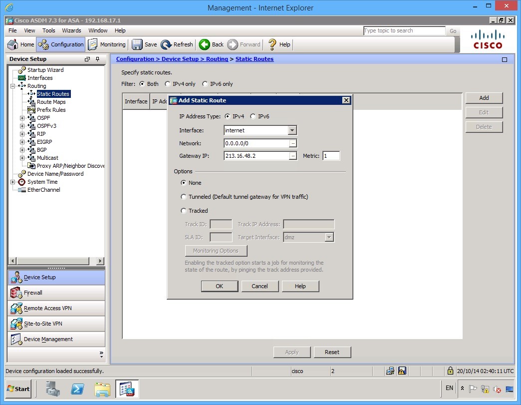 Figure 1.14 Cisco ASDM: The completed Add Static Route dialog box
Step 17
To apply the changes, click the Apply button.
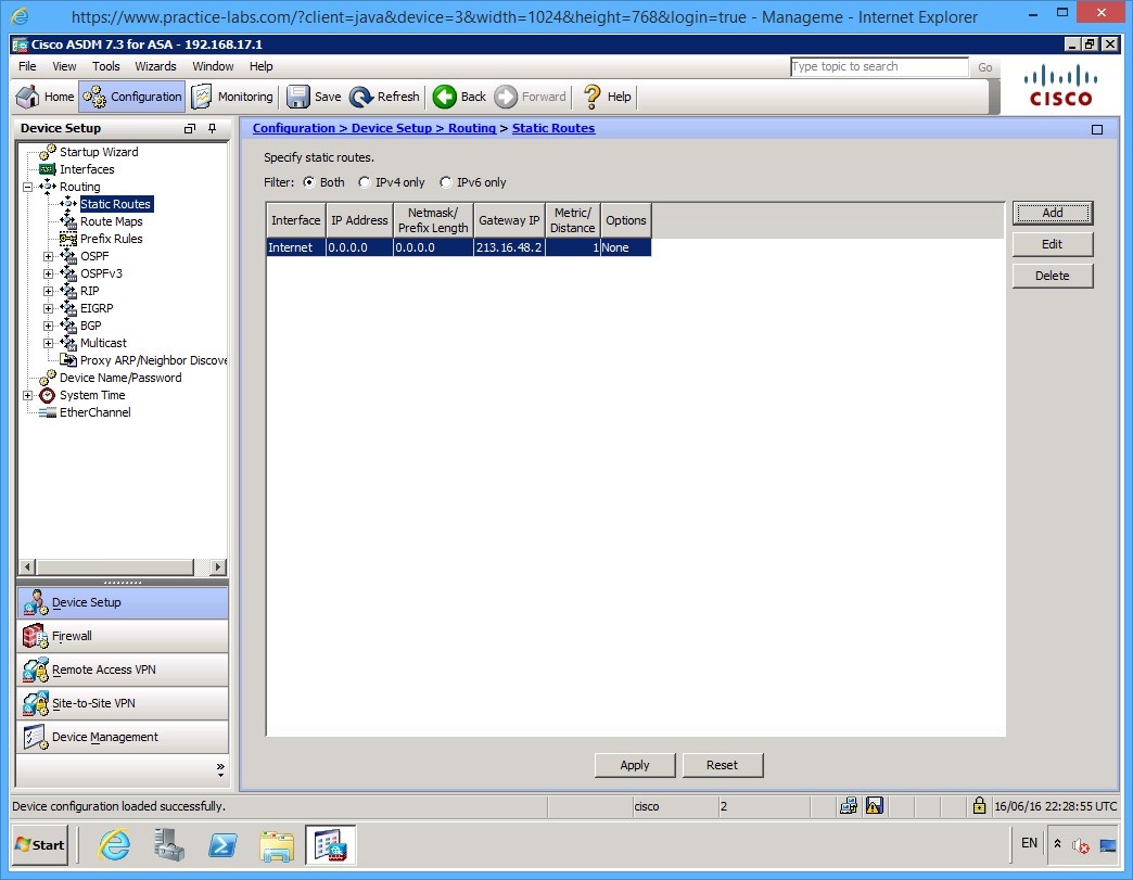 Figure 1.15 Cisco ASDM: The static route that was configured now shows up on the list of static routes.
Step 18
Before continuing to the next exercise where you will configure a policy, examine the default behavior of the firewall.
Open up Internet explorer on PLABMGMT and in the address bar, type: http://PLABDMZWEB. Note that you must put in the http:// otherwise it will go to Microsoft Bing to search for the host.
Your browse should be successful. Close Internet Explorer.
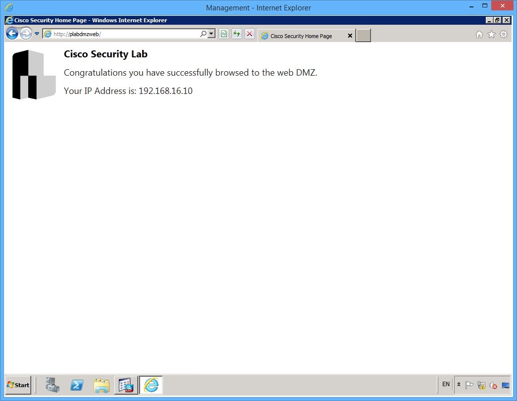 Figure 1.15 Cisco ASDM: Without any further configuration, web connectivity is available to the DMZ from PLABMGMT via the IP address of the PLABMGMT device.
Even though you have not configured any firewall policies, you can, by default, communicate from any higher level security interface to any lower level security interface. That is, you can browse, ping, telnet, etc. from the internal to the dmz and internet interfaces.
Leave your devices in their current states and continue to the next exercise.
Exercise 2 - Configuring NAT
In this exercise, you will configure NAT so that you can browse to PLABEXTCLI from PLABMGMT. This will take place using a valid routable Internet address for the PLABMGMT device and not its own private address. You will also configure a translation such that the PLABDMZWEB server will have a valid external IP address.
Task 1 - Configuring Dynamic PAT
First, configure PAT for all of the inside corporate devices. In the lab, of course, there is only PLABMGMT, but for a more real world scenario, you will configure PAT that will allow anything on the 192.168.16.0/24 subnet to be translated to a specific routable address.
For, PAT you will overload on to the ASA GigabitEthernet 0/3 interface IP address. In other words, any internal device on the corporate network that accesses the Internet will do so using the 213.16.48.1 external IP address.
Step 1
On the PLABMGMT device, the ASDM application should still be open. Click the Firewall tab on the left pane near the bottom of the screen.
Now click the NAT Rules link in the Firewall panel on the left.
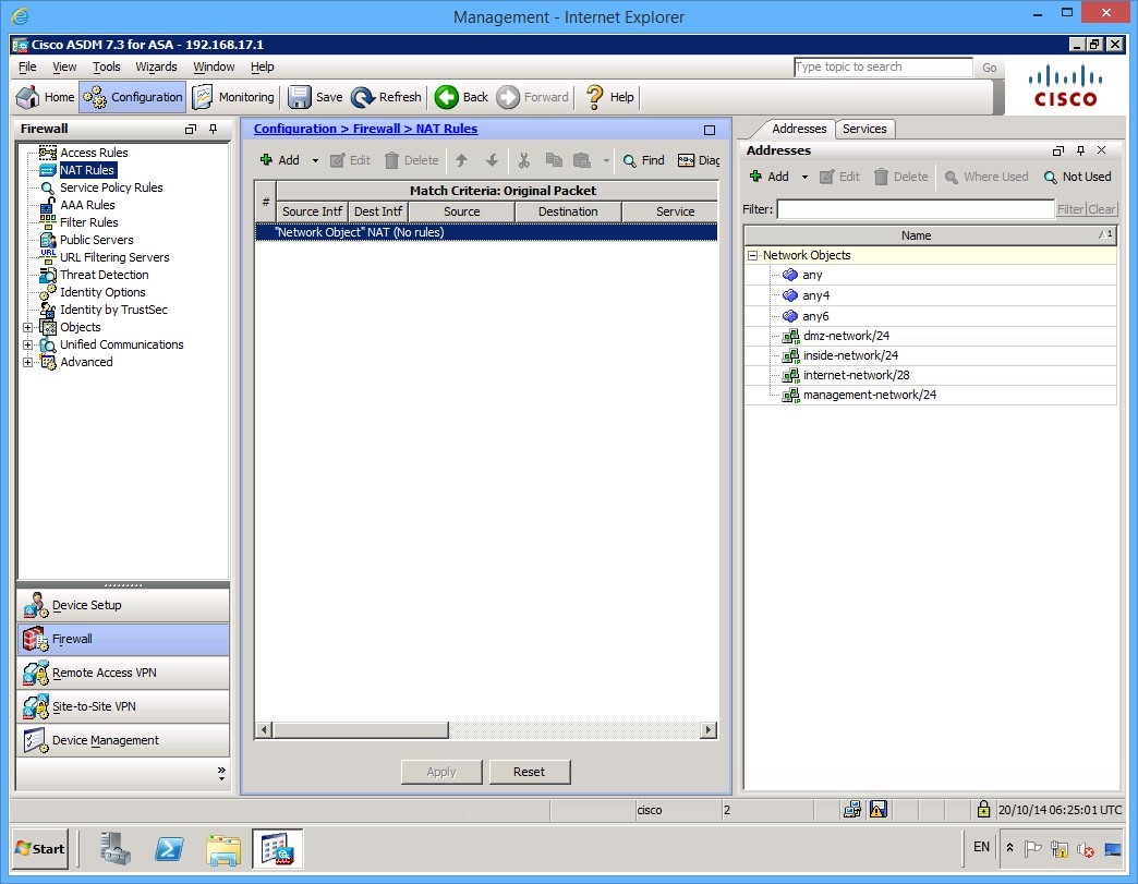 Figure 2.1 Cisco ASDM: The NAT Rules information panel is displayed.
Step 2
With the NAT panel open, click the dropdown menu of the Add button at the top of the page and select the Add NAT Rule Before “Network Object” NAT Rules… menu item.
Alert: Don’t click the Add button, but click on the little down arrow beside the Add button to get a menu as shown in the figure.
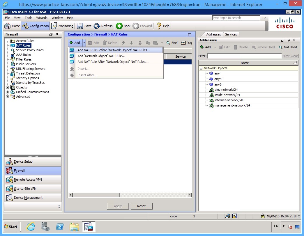 Figure 2.2 Cisco ASDM: Choose Add NAT Rule Before “Network Object” NAT Rules… menu item.
Step 3
Here you are presented with necessary NAT parameters. You will overload the inside network destined to the Internet and the action will be to PAT the source address (Dynamic PAT Hide). Use the following settings to achieve this:
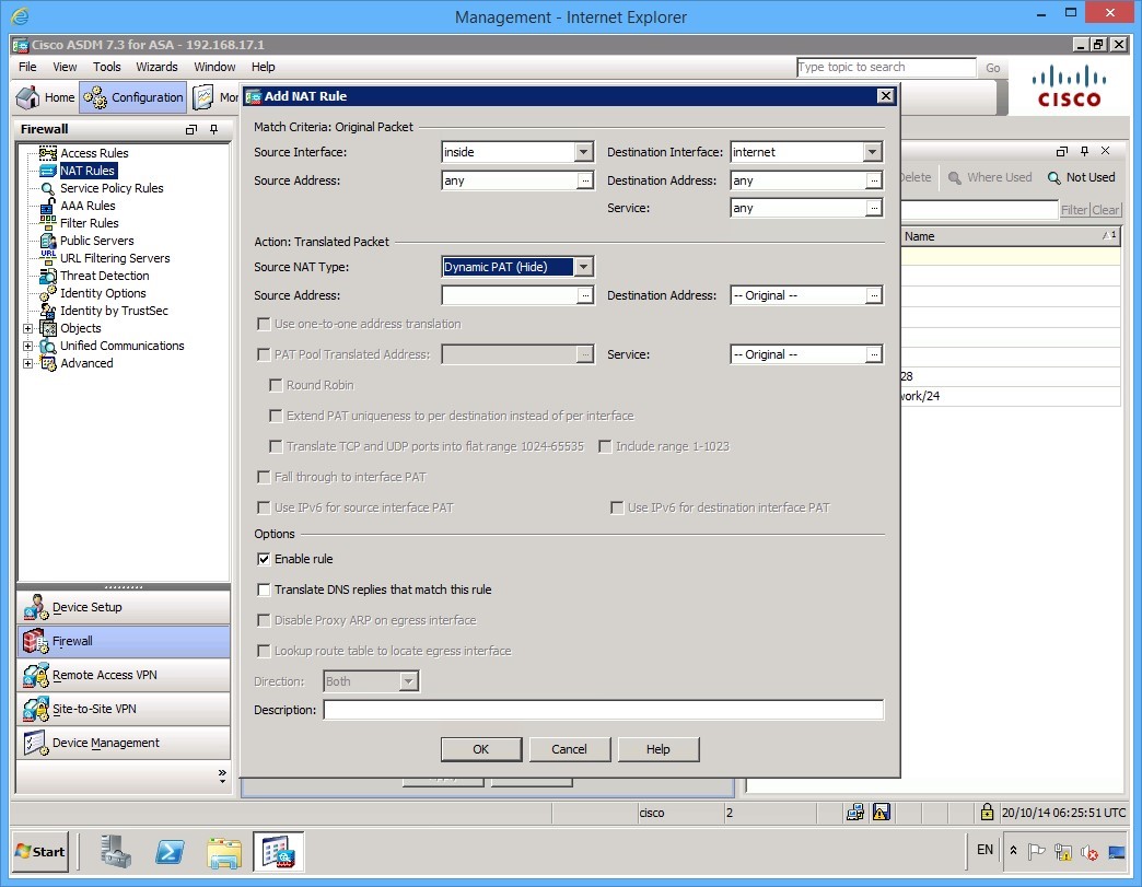 Figure 2.3 Cisco ASDM: Parameters for configuring NAT.
Step 4
Within the Action: Translated Packet settings, click the […] button next to the Source Address. You will get a new dialog window popup as shown in the following figure:
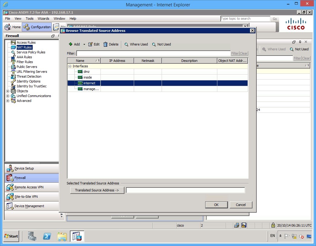 Figure 2.4 Cisco ASDM: Browse Translated Source Address dialog box.
Step 5
To choose the appropriate translated source address interface, double-click on the internet interface. The Translated Source Address field should now be populated. Click OK when done.
Step 6
Your settings should now look like this on the Add NAT Rule dialog box.
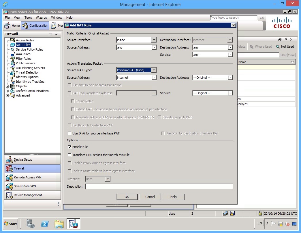 Figure 2.5 Cisco ASDM: Parameters for configuring NAT.
Notice that you are not changing the destination address, or specifically setting what source IP network the traffic is coming from. You may want to do this in a production environment to assign different external routable addresses to different networks for example. Click OK to accept these parameters.
Step 7
Click Apply to commit your changes.
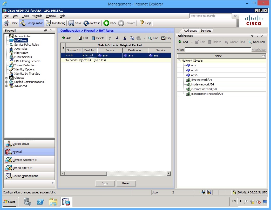 Figure 2.6 Cisco ASDM: The NAT Rules information panel is displayed after the configuration has been applied.
Step 8
Open up Internet explorer if you closed it in the previous exercise. In the address bar, enter in http://PLABEXTCLI. Press Enter.
Notice the IP address that is displayed on the web page. You have connected to the website with an IP Address of 213.16.48.1 which is the address you configured on GigabitEthernet0/3 on the ASA.
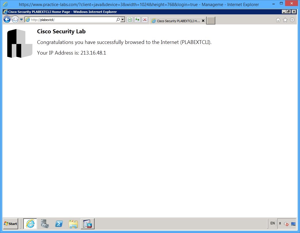 Figure 2.7 Cisco ASDM: You have connected to the web server using the external IP address of the ASA.
You have successfully configured PAT on the ASA. Close Internet Explorer and keep the ADSM window open before going on to the next section.
Task 2- Configuring Static NAT Translation
To setup translation between two network addresses, follow these steps:
Step 1
On PLABMGMT device, the ADSM window should be open. You will configure translation to allow PLABEXTCLI to be able to browse to PLABDMZWEB.
First, create two objects in the firewall, one for the NAT’d address of the web server, or the external routable address, and the other for the internal address, which is the actual address of the server.
- External address: 213.16.48.5 /32
- Internal address: 172.16.16.10 /32
To configure these objects, if you have not already done so, click the Firewall tab and then the NAT Rules option in the pane on the left. On the right hand side under the Addresses tab, click the Add drop-down button and then click Network Object…
Alert: Don’t click the Add button, but click on the little down arrow beside the Add button to get a menu as shown in the figure.
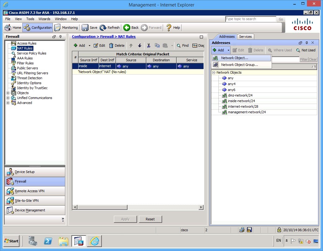 Figure 2.8 Cisco ASDM: Click on Network Object… from the Add drop-down menu.
Step 2
You will configure a network object that corresponds to the external routable IP address that will be used by the PLABDMZWEB server. In the dialog that appears, type the relevant names, and IP addresses, leaving the Type as Host.
Specifically, configure the Name of the network object as nat-PLABDMZWEB with an IP Address of 213.16.48.5:
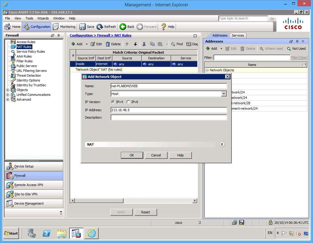 Figure 2.8 Cisco ASDM: Configuring the Network Object for the external IP address of the web server.
Notice that there is a NAT drop down in this section. Click the dropdown arrows and make sure that the Add Automatic Address Translation Rules check box is cleared. No additional NAT configuration will be implemented here as you will a NAT rule instead.
Once you have finished, click OK.
Step 3
Create a second NAT object in the same manner for the internal private address of the web server. For this network object, you will use the name srv-PLABDMZWEB. Again, under the NAT dropdown section, clear the Add automatic Address Translation Rules check box.
Click OK when done.
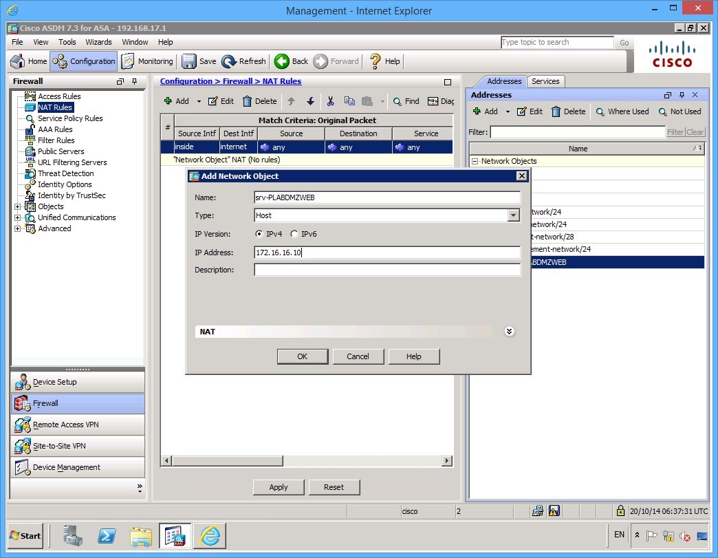 Figure 2.9 Cisco ASDM: Configuring the Network Object for the internal IP address of the web server.
Step 4
You should now have your two new objects on the pane to the right.
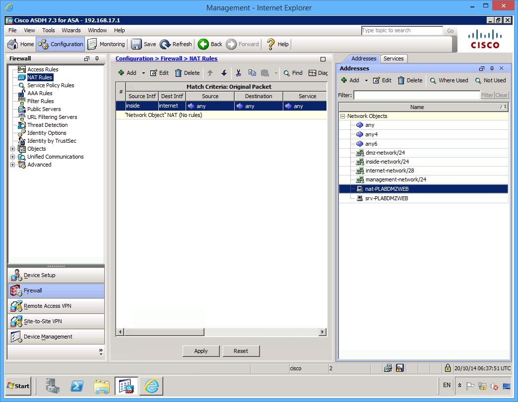 Figure 2.10 Cisco ASDM: The two new network objects can be seen on the list in the pane to the right.
Step 5
With the network objects configured, you will now configure the NAT rule. Click on the Add button in the center pane.
Alert: This time, don’t click on the little down arrow beside the Add button, but on the Add button itself.
The Add NAT Rule dialog box appears. Configure a NAT rule with the same configuration as that in the following figure.
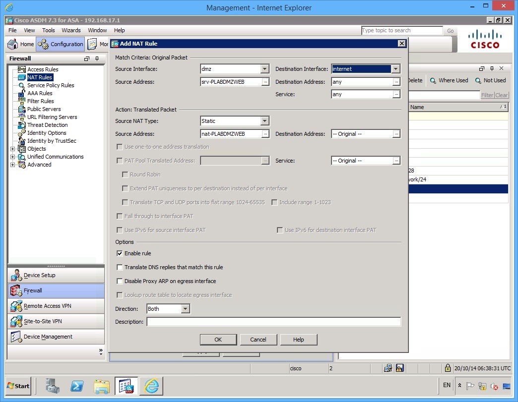 Figure 2.11 Cisco ASDM: Configuring the NAT rule.
Ensure you have enabled the rule and click OK.
Step 6
Apply your configuration once you have created the rule by clicking the Apply button. Notice that the ASDM software creates two rules and lists them in the center pane:
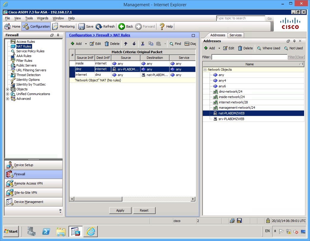 Figure 2.12 Cisco ASDM: The new rule is applied, and the ASA adds two new rules to the list.
Step 7
Connect to PLABEXTCLI and launch Internet Explorer. Try and browse to PLABDMZWEB.
Alert: Don’t forget to use the http:// before the web server name.
Notice that the connection fails. It may take several minutes for the web page to refresh. This is because of an access rule allowing the inbound traffic has not yet been created. Remember that lower security interfaces cannot communicate with higher security interfaces.
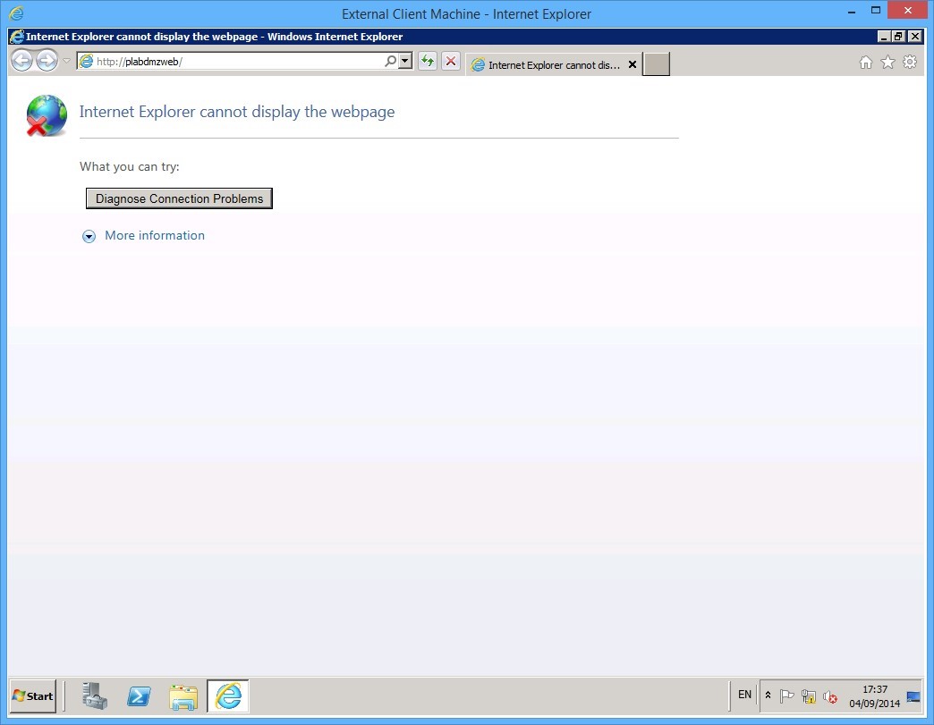 Figure 2.13 Cisco ASDM: The connection to the web server fails.
In the next exercise, you will configure an access rule that will allow this communication to occur.
Leave your devices powered on and in their current states and continue to the next exercise.
Exercise 3 - Configuring a Security Policy
In this exercise, you will configure a policy to allow Internet based devices to browse into your webserver PLABDMZWEB.
This will complete the basic configuration of the Cisco ASA firewall.
Task 1 - Setting up Access Rule
To configure this access rule, use the following steps:
Step 1
Connect to the PLABMGMT device. In the ASDM software, click the Configuration button and then ensure the Firewall tab is selected at the left.
Click the Access Rules link at the top of the left hand panel:
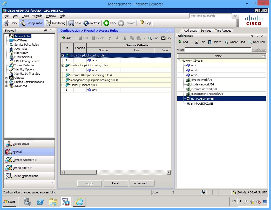 Figure 3.1 Cisco ASDM: The Access Rules are displayed.
Step 2
Notice that the default policy does show that an interface will forward to any less secure interface. As soon as you apply a rule, this behaviour stops, and only the policy you apply is adhered to.
To create a rule, click the Add button at the top of the page, then select Add Access Rule.
Alert: Don’t click the Add button, but click on the little down arrow beside the Add button to get a menu as shown in the figure.
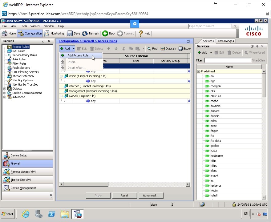 Figure 3.2 Cisco ASDM: To create a rule, click the Add button at the top of the page, then select Add Access Rule.
Step 3
Because you require Internet hosts to come inbound to the webserver, select the internet interface. The action should be Permit as you want to allow the traffic.
The Source should be any but the Destination and Service must be changed to the web server IP address and of course, to allow http. You could allow https as well if you choose to.
Your rule should look like this:
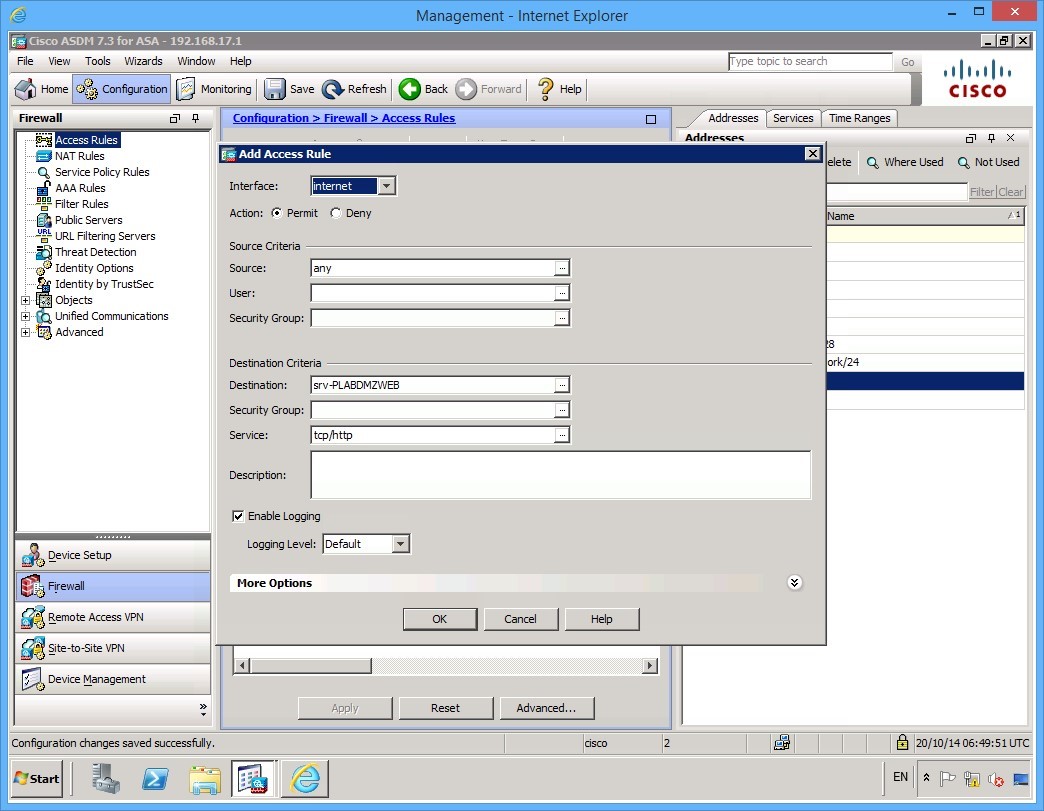 Figure 3.3 Cisco ASDM: The configuration parameters of the access rule.
Step 4
Click OK and then click the Apply button when it becomes available to apply your new rule.
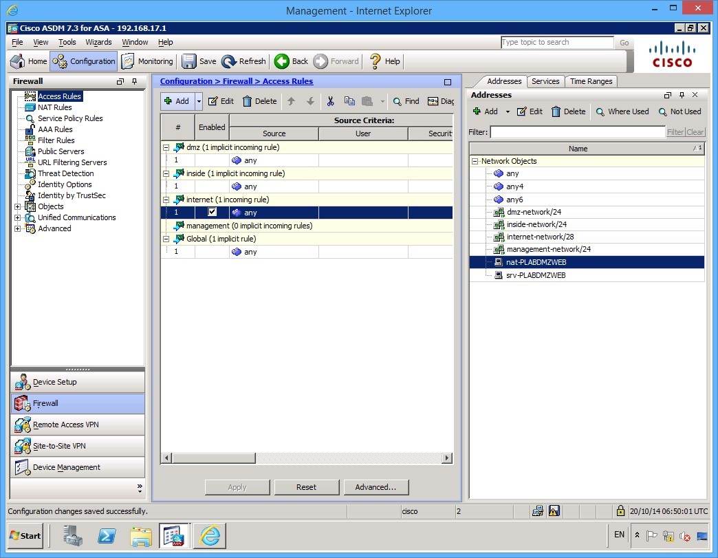 Figure 3.3 Cisco ASDM: The new rule appears in the Access Rules pane.
Step 5
Connect to the PLABEXTCLI device. Launch Internet Explorer and try to browse to http://PLABDMZWEB web page. The connection now works.
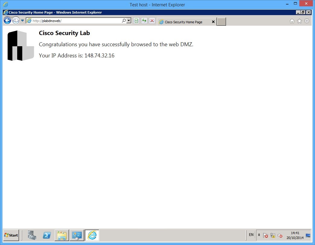 Figure 3.3 Cisco ASDM: After the new access rule has been applied, the connection to the web server functions correctly.
Task 2 - Anti-Spoofing
It is good practice to enable Anti-spoofing on all firewalls, where possible. This is a very simple task that will help against attacks.
To enable anti-spoofing, follow these steps:
Step 1
On PLABMGMT device, go to the ASDM configuration tab, then click Firewall tab at the bottom left.
In the Firewall options, expand Advanced and click Anti Spoofing:
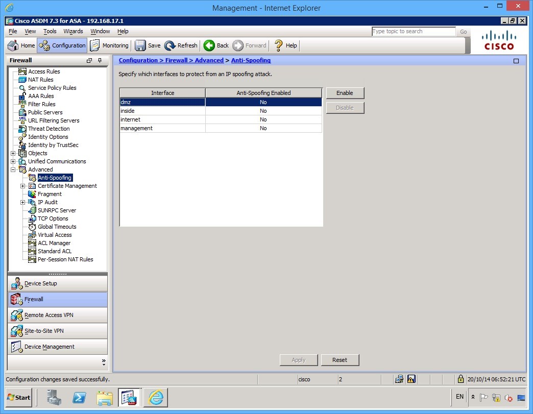
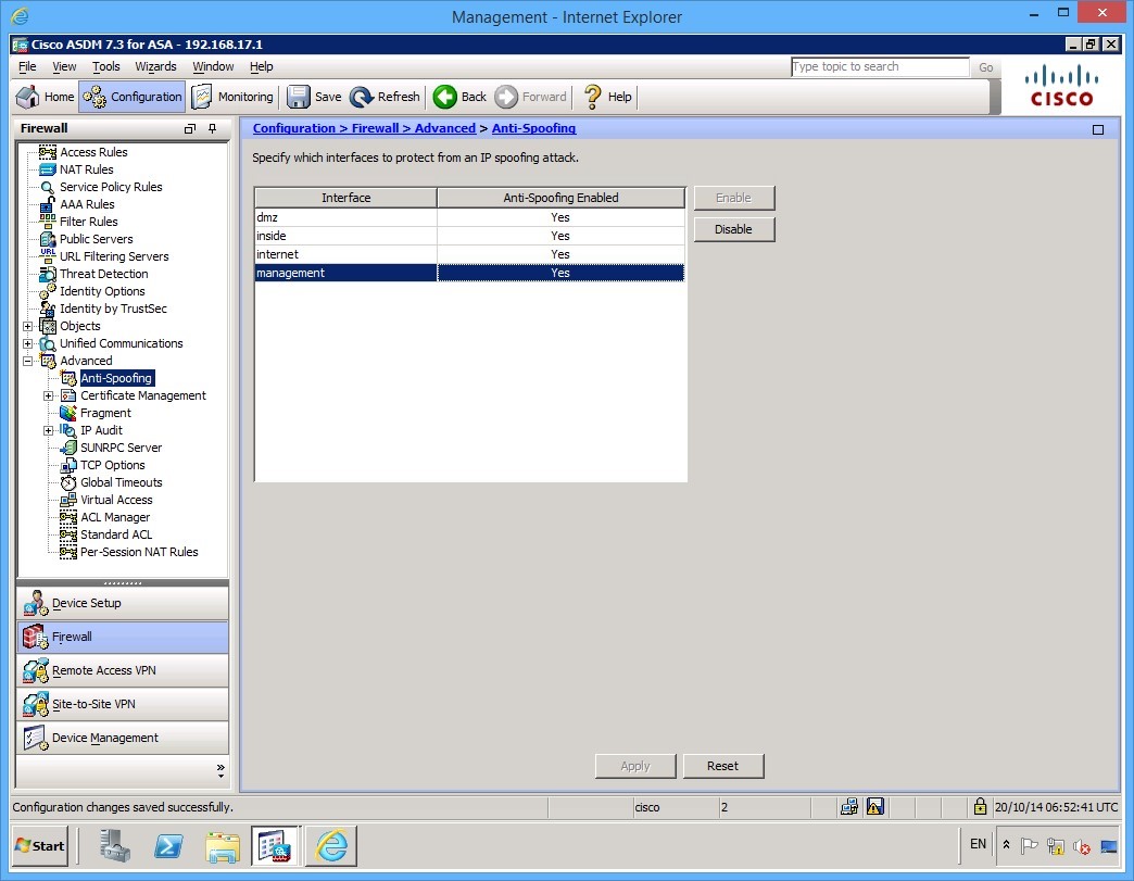
Enable anti-spoofing on all the interfaces by selecting each Interface, then click Enable, as always click Apply when done.
Task 3 - Setting the System Clock
Accurate system time is critical for tracing logs in firewalls, so it’s an important task that every firewall engineer should understand how to complete. If you have an NTP server you should consider synchronising your firewall estate with NTP, however, if you don’t (you may want to use a secure internet based NTP server), or alternatively use the internal clock on the ASA.
To set the internal clock use the followings steps:
Step 1
On PLABMGMT device, the ASDM application is open.
Click the Configuration button at the top of the ASDM software, then click Device Setup in the left hand panel at the bottom:
Step 2
Next, expand the System Time link in the left panel, and click Clock.
Set the correct time zone, for this example, we will use GMT 00:00 (UTC: London) and set the clock to 14:30:00.
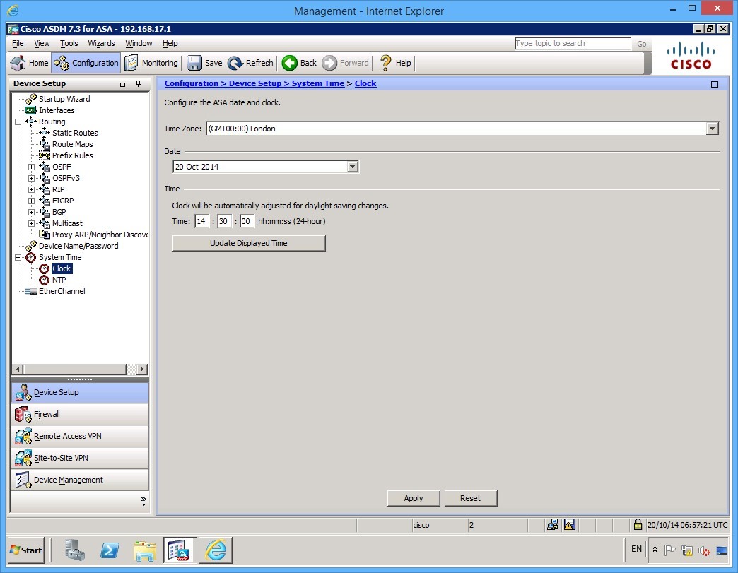
As always, click Apply to commit the configuration.
Task 4 - Management Access
At current, the only remote communication to the firewall is through the ASDM on the management interface. If you wanted to change this, for example, you don’t have the luxury of having a management network, or you want to enable SSH access, this can be done in the Device Management > Management access section.
Complete these steps to add SSH (version 2 only) access via the management interface.
Step 1
On PLABMGMT device, click on the configuration button at the top of the ASDM software, then click Device Management in the bottom left if it’s not already selected.
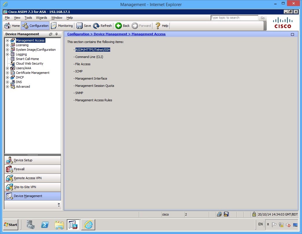
Step 2
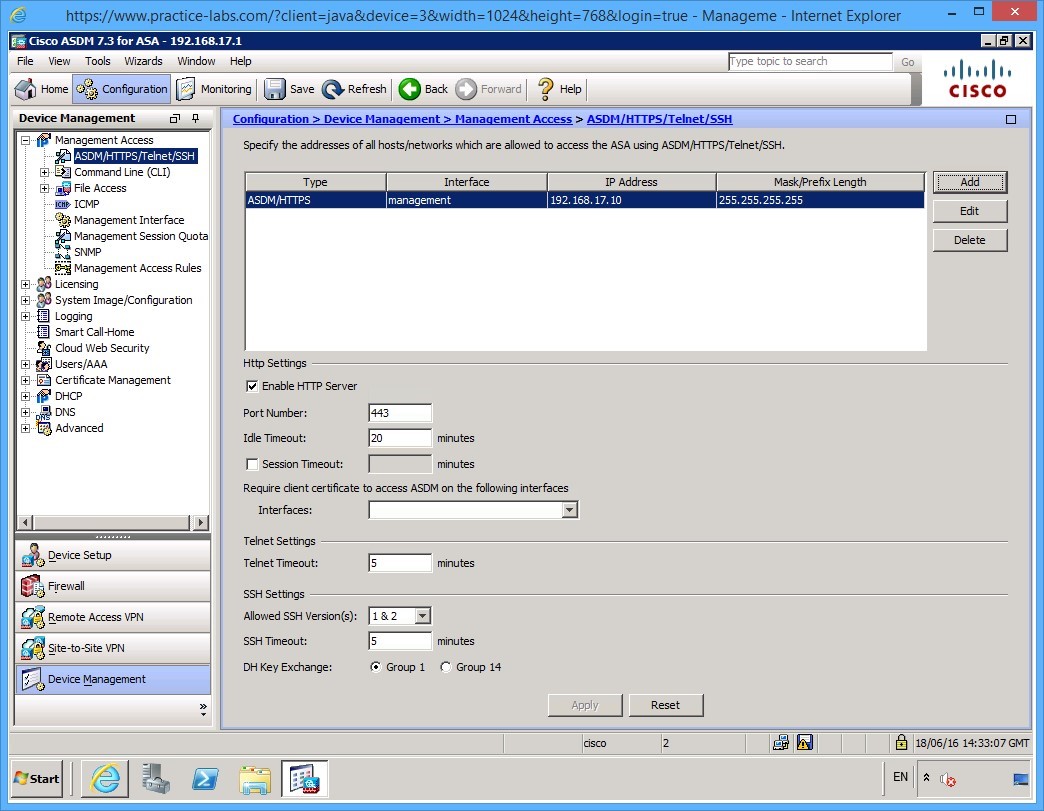
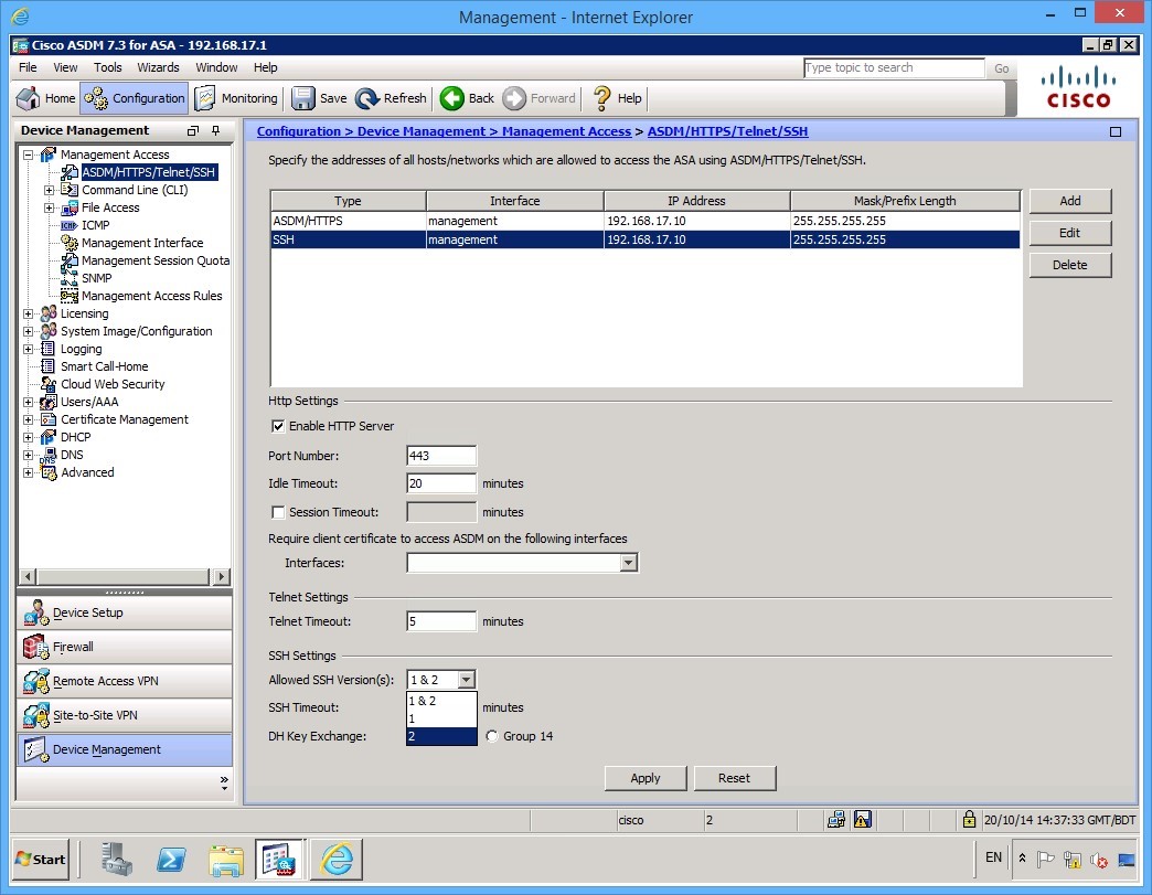
Expand the Management Access node, then click ASDM/HTTPS/Telnet/SSH. In this example, we will add SSH access, click the Add button on the far right.
Step 3
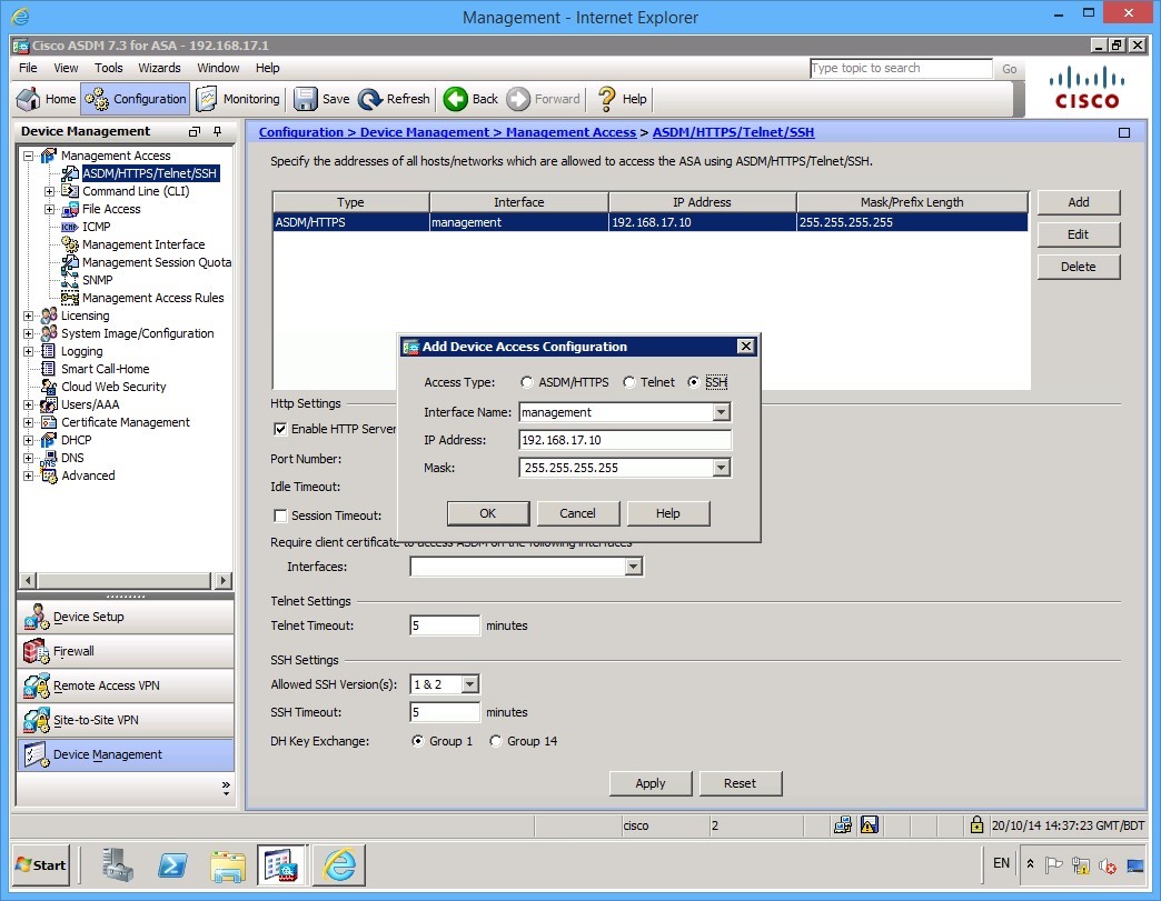
Create the following configuration:
- Access Type: SSH
- Interface Name: Management
- IP Address: 192.168.17.10
- Mask: 255.255.255.255
Once you have entered the details, click OK.
This will enable PLABMGMT to communicate via SSH.
Step 4
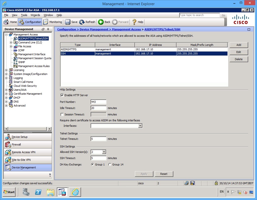
Before applying the configuration, change the Allowed SSH Version(s) to be 2 only.
Step 5
Then click Apply.
Keep the ASDM window open.
Leave your devices powered on and in their current states and continue to the next exercise.
Exercise 4 - Modular Policy Framework
In this exercise, you will create a default modular policy framework (MPF) that the ASA will use to inspect traffic.
Ensure you are still connected to PLABMGMT and you are logged into the ASDM software.
Task 1 - Configuring the Policy Framework
To create a default policy, follow these steps:
Step 1
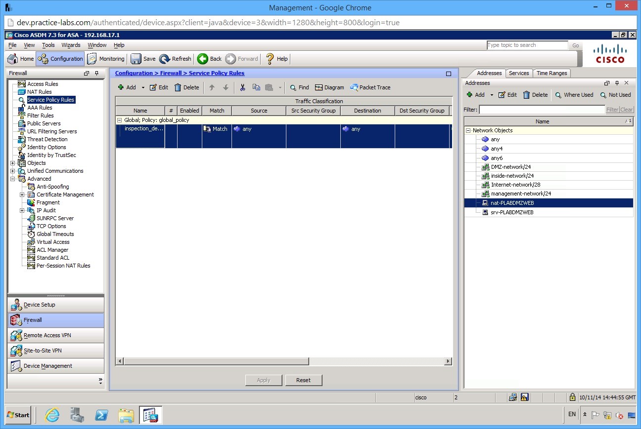
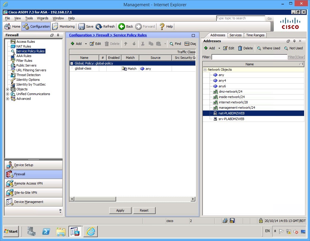
On PLABMGMT device, ASDM window is open.
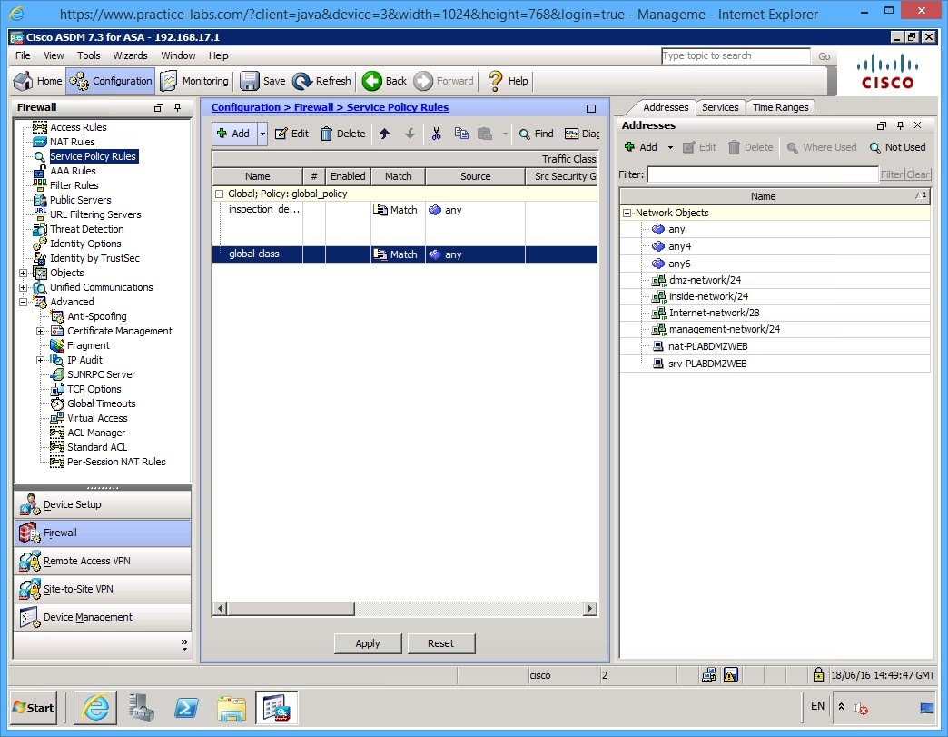
Click the Configuration button and ensure that the Firewall tab is selected at the bottom. In the panel on the left, you will see a link for Service Policy Rules, click this link and the centre panel changes to the policy rules.
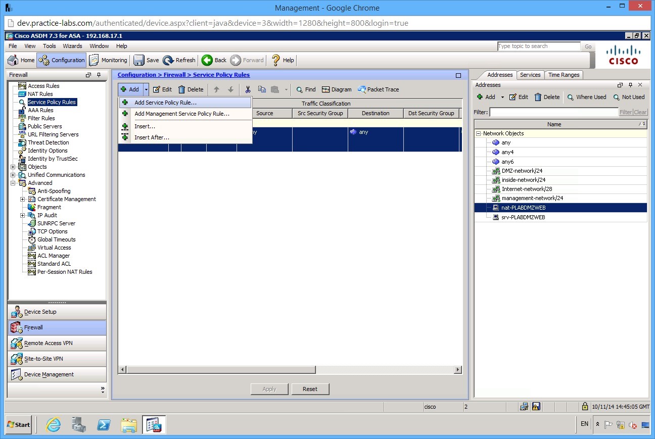
Step 2
To create a new policy click the Add button at the top of the page (click the down arrow) and select Add Service Policy Rule…
Step 3
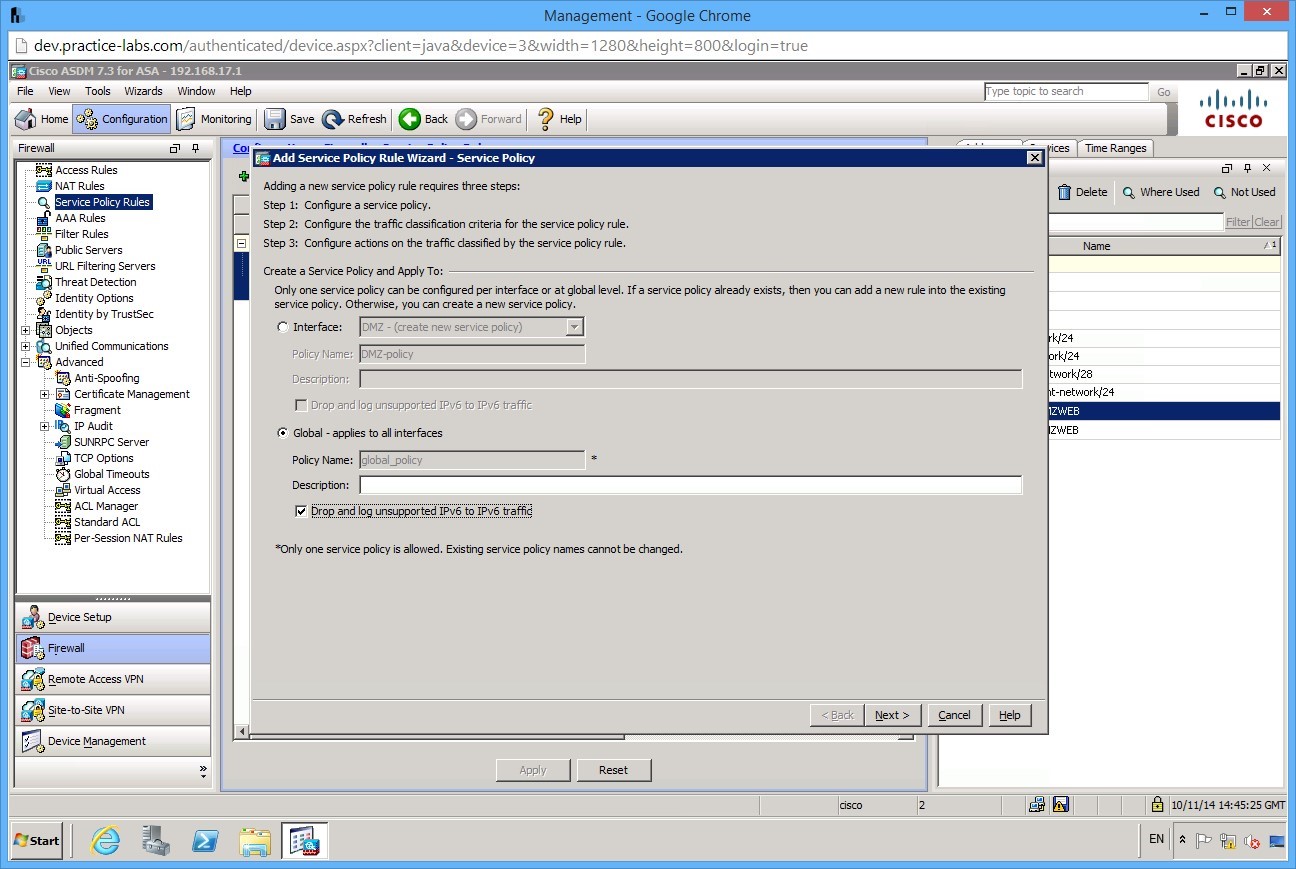
On the first page of the wizard you will notice that we have a note at the bottom of the page (Only one service policy is allowed), select the checkbox that says Drop and log unsupported IPv6 to IPv6 traffic then click Next:
Step 4
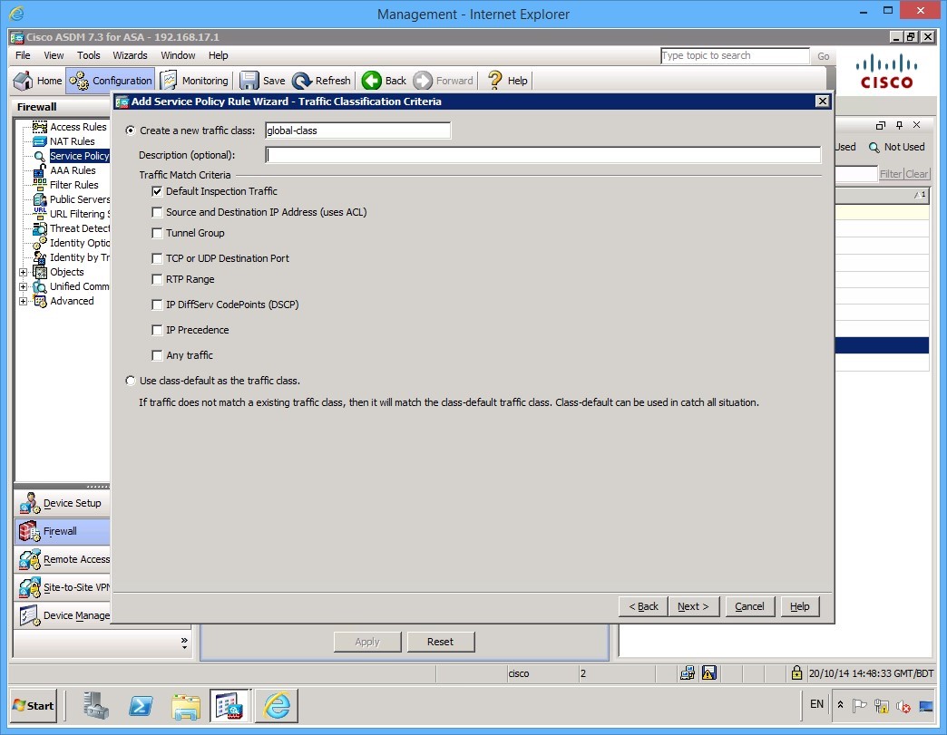
On the Traffic Classification Criteria page, select Default Inspection Traffic check box. It’s important to understand the difference between these options if you are unsure which option you need in your production environment click the Help button which gives you an explanation of each to ensure you are checking the right option here. In our example we will use the Default Inspection Traffic option, the help page gives us this description:
 - Default Inspection Traffic—The class matches the default TCP and UDP ports used by all applications that the ASA can inspect.
This option, which is used in the default global policy, is a special shortcut that when used in a rule, ensures that the correct inspection is applied to each packet, based on the destination port of the traffic. For example, when UDP traffic for port 69 reaches the ASA, then the ASA applies the TFTP inspection; when TCP traffic for port 21 arrives, then the ASA applies the FTP inspection. So in this case only, you can configure multiple inspections for the same rule (See Incompatibility of Certain Feature Actions for more information about combining actions). Normally, the ASA does not use the port number to determine the inspection applied, thus giving you the flexibility to apply inspections to non-standard ports, for example.
See Default Settings and NAT Limitations, page 45-4 for a list of default ports. The ASA includes a default global policy that matches the default inspection traffic, and applies common inspections to the traffic on all interfaces. Not all applications whose ports are included in the Default Inspection Traffic class are enabled by default in the policy map.
You can specify a Source and Destination IP Address (uses ACL) class along with the Default Inspection Traffic class to narrow the matched traffic. Because the Default Inspection Traffic class specifies the ports and protocols to match, any ports and protocols in the ACL are ignored.
Click Next when you are happy.
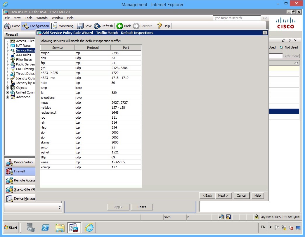
Step 5
This next screen shows the summary default inspections with their protocol and port numbers or ranges.
Click Next.
Step 6
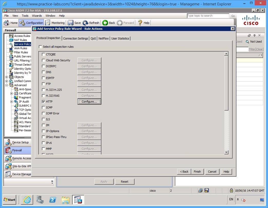
Next, we can select our rule actions. In this example, we’ll enable HTTP only. Of course in your production environment, you will want to know exactly what is flowing through your firewall and enable the appropriate settings.
Once you click the checkbox for HTTP click the Configure button.
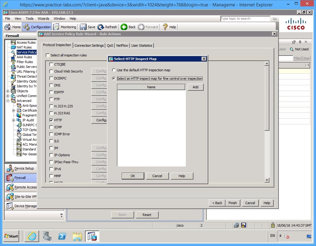
Step 7
Just so you can see the options, click the Select an HTTP inspection map for fine control over inspection radio button, then click Add.
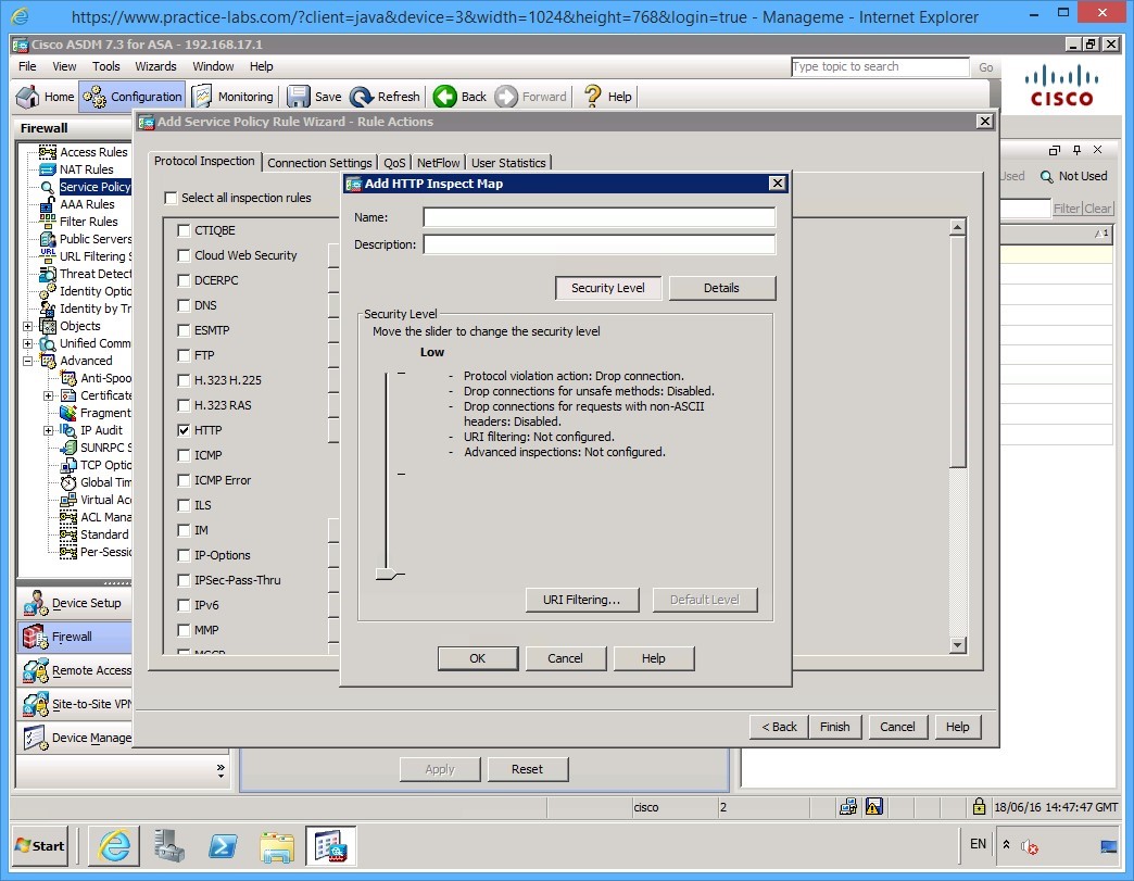
Step 8
Here you have some advanced settings that you can configure. Feel free to have a look at these settings. For this example, however, cancel out of this.
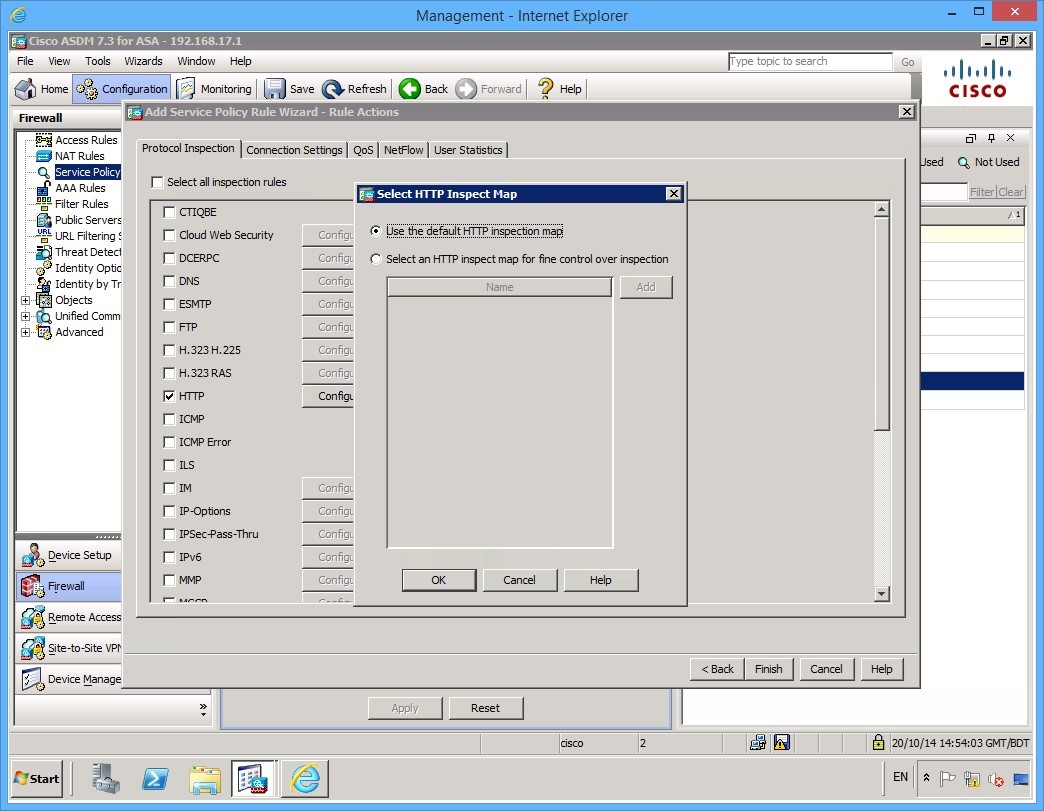
Step 9
Back on the Select HTTP Inspect Map dialog box, ensure that the Use default HTTP inspection map radio button is selected.
Click OK.
Step 10
Then click Finish on the Service Policy Rule Wizard.

Step 11
As always, click Apply to send your configuration to the ASA.
This completes your basic configuration of the ASA.
Shut down all the virtual machines and devices used in this exercise using Practice Labs power button function to revert this device to its default settings.
Alternatively, you may sign out of the lab portal to power down all device.
Shut down all virtual machines used in this exercise using Practice Labs power button function to revert these devices to their default settings. Alternatively, you may sign out to power down all devices.
Summary
In this module, you configured the ASA firewall to enable you to remotely connect using the ASDM software. Once you were connected, you then used the ASDM software to create some NAT rules and a basic firewall policy allowing your corporate users to browse out to the Internet and to enable Internet users to access your Web server located on a DMZ that you configured.
You covered the following activities in this module:
- Configured core ASA features
- Configured NAT
- Configured a security policy
- Viewed the default modular policy framework.