Southern New Hampshire University | SNHU-CYB210: Computer Networking
Configure IPv4, IPv6 Addressing and Routing
Exercises
- Introduction
- Exercise 1 - Configure the Network to use an ISATAP Router
- Exercise 2 - Setup Network Connectivity between IPv4 and IPv6 devices
- Exercise 3 - Static Routing
- Exercise 4 - Dynamic Routing
- Summary
Introduction
The Configure IPv4, IPv6 Addressing and Routing module provides you with the instruction and server hardware to develop your hands on skills in the defined topics. This module includes the following exercises:
- Configure the Network to use an ISATAP Router
- Setup Network Connectivity between IPv4 and IPv6 devices
- Static Routing
- Dynamic Routing
dc640c20-9434-45ea-b7c2-6d4d6a196bfc
Lab Diagram
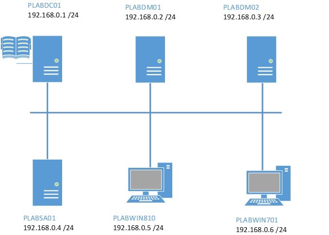
During your session you will have access to the following lab configuration.
Connecting to your lab
In this module you will be working on the following equipment to carry out the steps defined in each exercise.
- PLABDC01 (Domain Controller)
- PLABDM01 (Domain Member Server)
- PLABSA01 (Standalone Server)
- PLABWIN810 (Windows 8.1 Workstation)
To start, simply choose a device and click Power on. In some cases, the devices may power on automatically.
For further information and technical support, please see our Help and Support page.
Copyright © Practice Labs 2007 - 2018. All rights reserved.
Exercise 1 - Configure the Network to use an ISATAP Router
Intra-site Automatic Tunnel Addressing Protocol or ISATAP is a bridge-over technology that enables IPv4-only networks and devices to communicate with the more evolved IPv6-only counterparts. In this context, an ISATAP router is an essential element of any network that can be utilized to communicate with the more advanced IPv6 networks or devices; or is to be itself upgraded from the current IPv4 support to IPv6 support. ISATAP is a built-in feature for Windows Vista and later, and Windows Server 2008 and later versions.
You configure a Windows Server 2008 R2 host to operate as an ISATAP router. The configuration enables the host to send out messages offering ISATAP addressing and routing information to the ISATAP-enabled devices. This configuration uses CLI commands as, currently, no GUI is available to configure these hosts.
To better understand this technology, refer also to your course material or use your preferred search engine to research this topic in detail.
In this exercise, you will configure one of the hosts on the network to operate as an ISATAP router.
Task 1 - Configure a static IP address for PLABWIN810 second network interface
A Windows computer can function as a software-based router by installing a secondary network interface card and then configure a static IP address on this interface.
You will use NETSH to configure the secondary network interface of PLABWIN810 with a fixed IP address.
Step 1
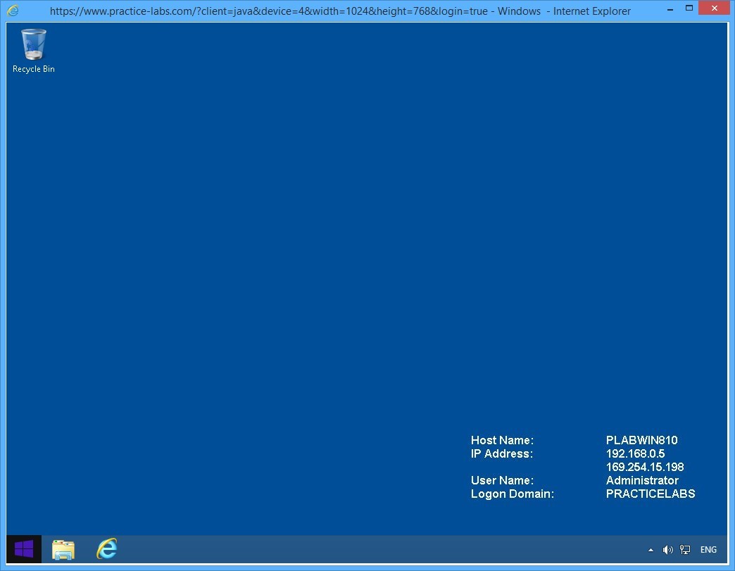
Connect to PLABWIN810.
On the desktop, click the Start charm to display the Start screen.
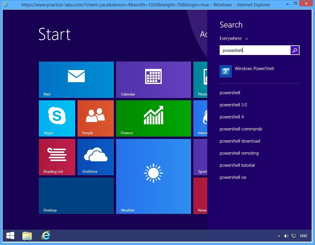
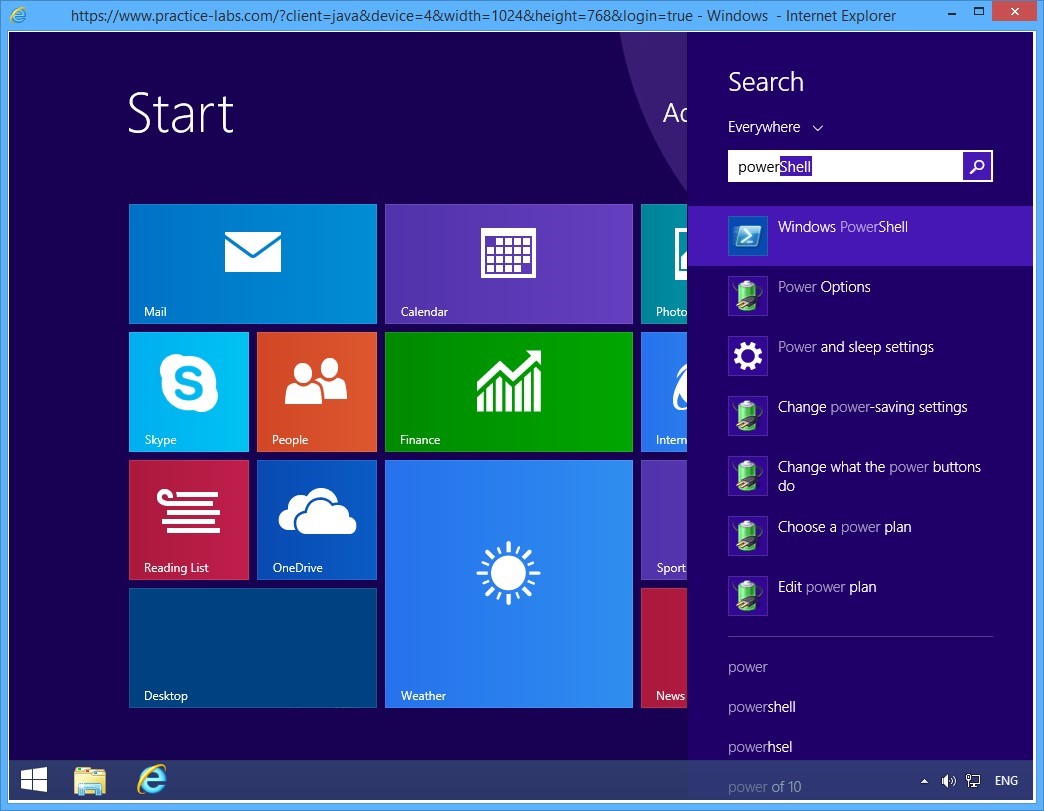
Step 2
On the Start screen, type powershell and press Enter.
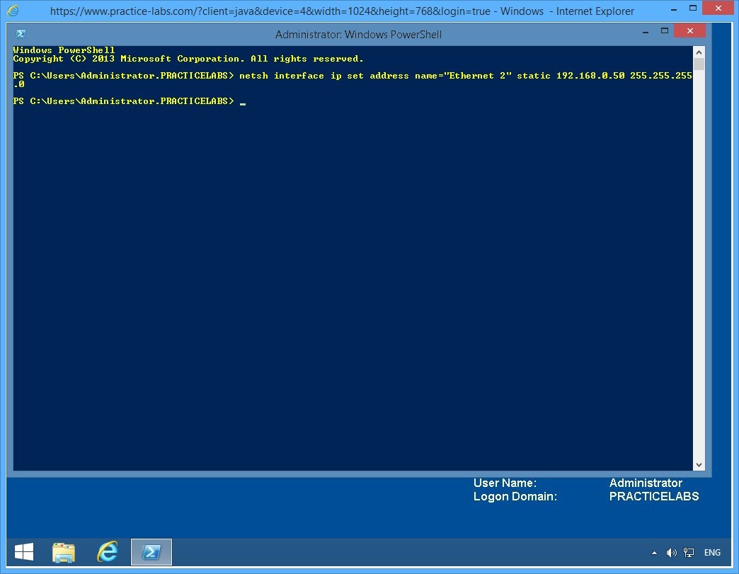
Step 3
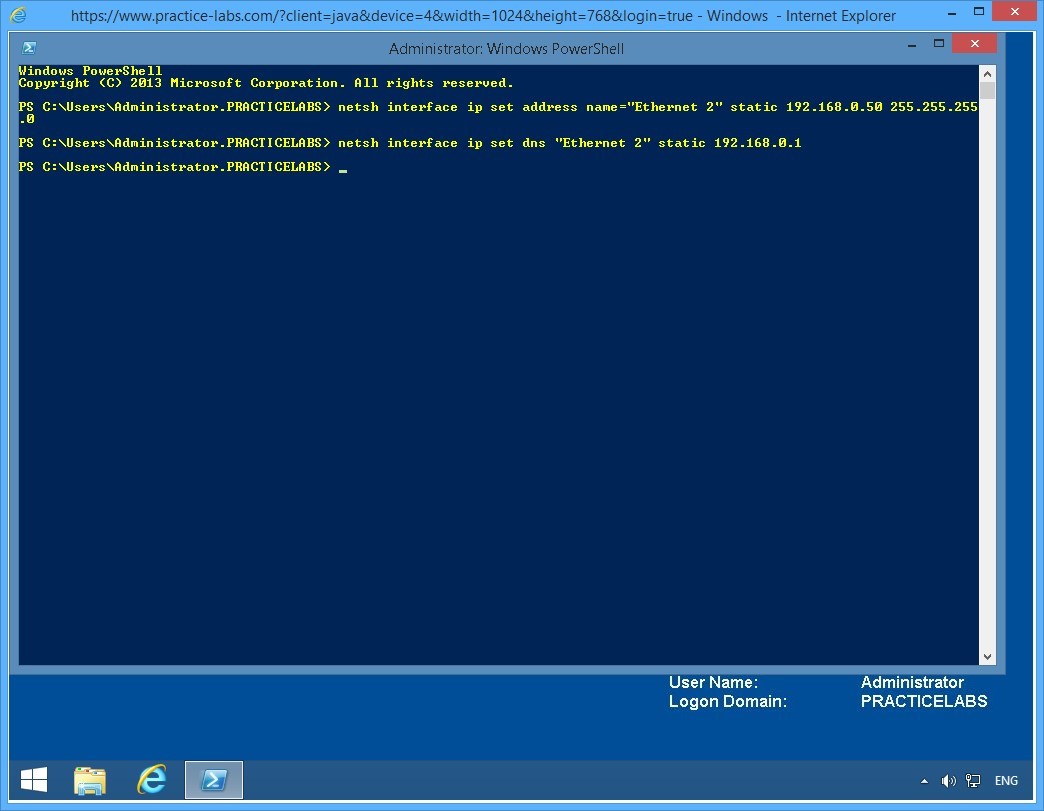
On the Windows PowerShell window, type the following command:
netsh interface ip set address name="Ethernet 2" static 192.168.0.50 255.255.255.0
Press Enter.
The above command sets a static IP address of 192.168.0.50 in PLABWIN810’s Ethernet 2 network connection.
Step 4
On the next PowerShell prompt, type the following command:
Netsh interface ip set dns "Ethernet 2" static 192.168.0.1
Press Enter.
This command configures Ethernet 2 network connection to use PLABDC01 - IP address 192.168.0.1 - as its Preferred DNS server.
Important: If you get an error saying “The configure DNS server is incorrect or does not exist” retry typing the same command. This error could be caused by network latency by PLABWIN810 getting a delayed response from PLABDC01.
Step 5
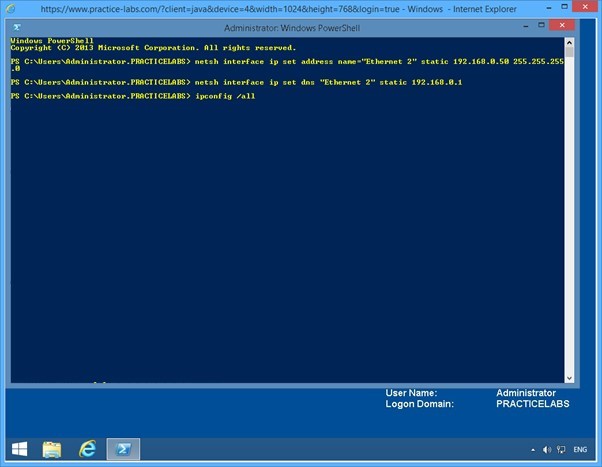
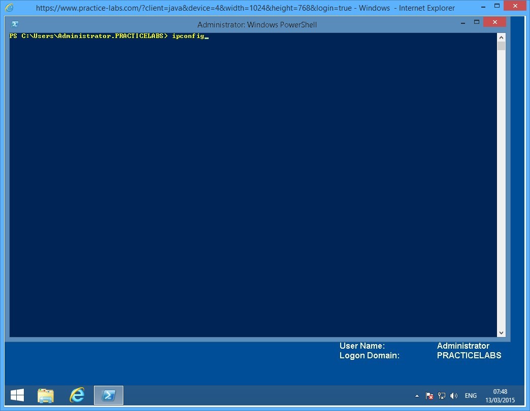
On the next PowerShell prompt, type:
Ipconfig /all
Press Enter.
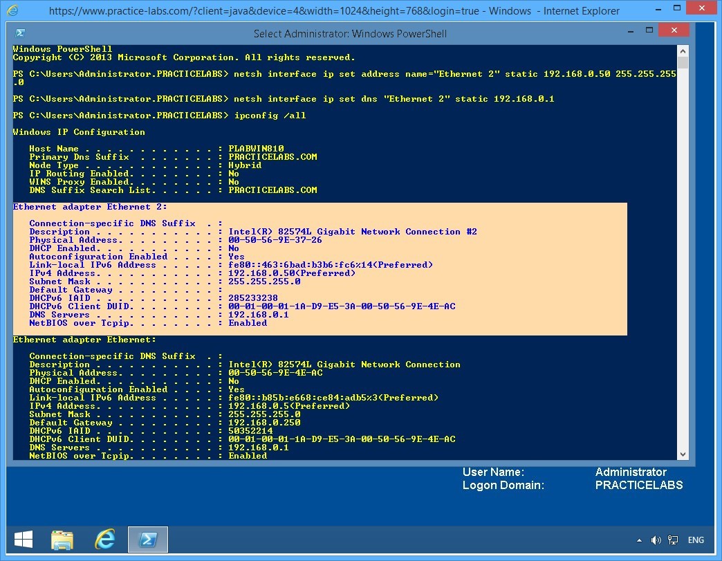
Step 6
From the IP configuration details displayed, verify that the Ethernet 2 interface is created and displays the configuration as specified in the preceding commands:
IPv4 Address: 192.168.0.50
Subnet Mask: 255.255.255.0
DNS Servers: 192.168.0.1
Close the Windows PowerShell window.
Keep all devices powered on in their current state and proceed to the next task.
Task 2 - Configure a static IP address in second network interface of PLABDM01
In this task, you will use NETSH to configure the second interface of PLABDM01 with a static IP address.
To configure a second interface for this domain server, perform the following steps:
Step 1
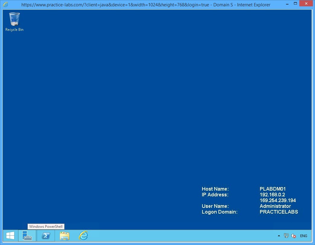
Connect to PLABDM01.
Click Windows PowerShell icon on the task bar.
Step 2
On the Windows PowerShell window, type the following command:
cd\
Press Enter.
On the next PowerShell prompt, type:
netsh interface ip set address name="Ethernet 2" static 192.168.0.20 255.255.255.0
Press Enter.
Minimize the PowerShell window.

Keep all devices powered on in their current state and proceed to the next task.
Task 3 - Configure a static IP address on PLABSA01’s second network interface
In this task, you will use NETSH commands to configure the second interface with static IP address for PLABSA01.
To configure a second interface for standalone server, perform the following steps:
Step 1
Connect to PLABSA01.
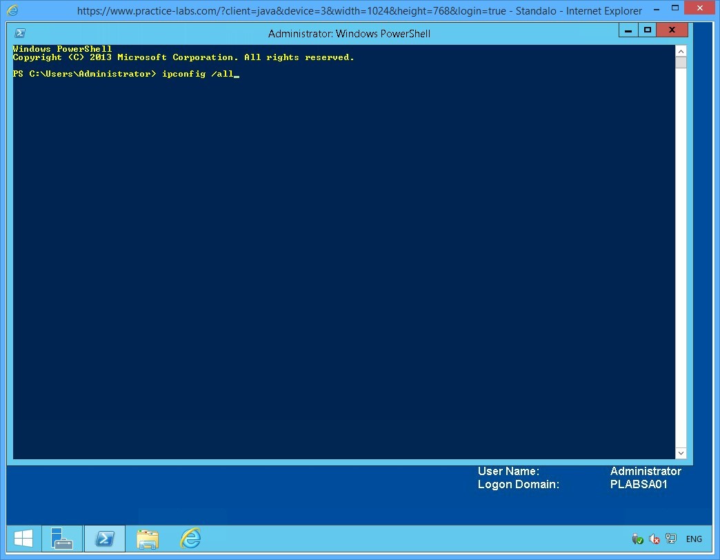
Click Windows PowerShell icon on the task bar.
Step 2
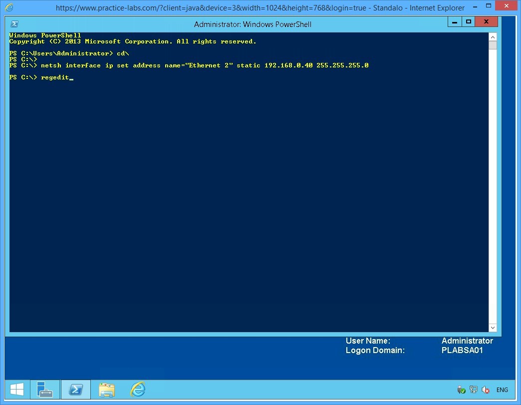
On the Windows PowerShell window, type the following command:
cd\
Press Enter.
On the next PowerShell prompt, type:
netsh interface ip set address name="Ethernet 2" static 192.168.0.40 255.255.255.0
Press Enter.
Leave the PowerShell window open.

Keep all devices powered on in their current state and proceed to the next task.
Task 4 - Enable IP Routing on PLABSA01
In this task, you will enable IP routing on PLABSA01.
To enable IP routing on the stand-alone server, perform the following steps:
Step 1
From PLABSA01, while in the PowerShell prompt, type regedit and press Enter.
Step 2
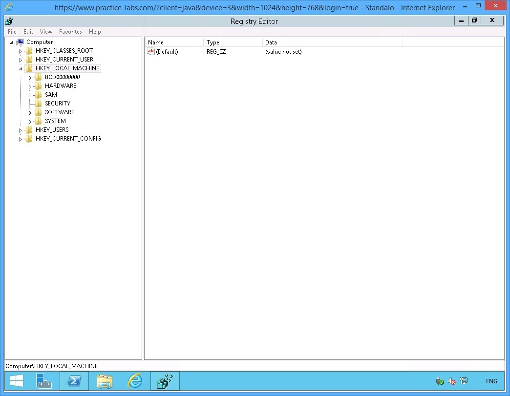
The Registry Editor window is displayed.
From the console tree on the left pane, expand the HKEY_LOCAL_MACHINE node, if not already expanded.
Step 3
Under the HKEY_LOCAL_MACHINE node, successively expand the SYSTEM-> CurrentControlSet > Services > Tcpip nodes.
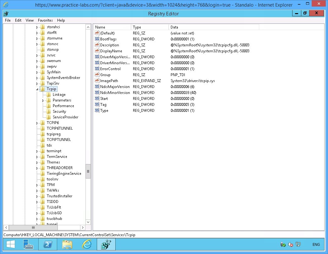
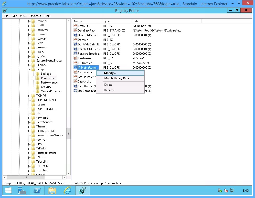
Step 4
Expand Parameters under the Tcpip node.
On the right pane, right-click IPEnableRouter and select Modify.
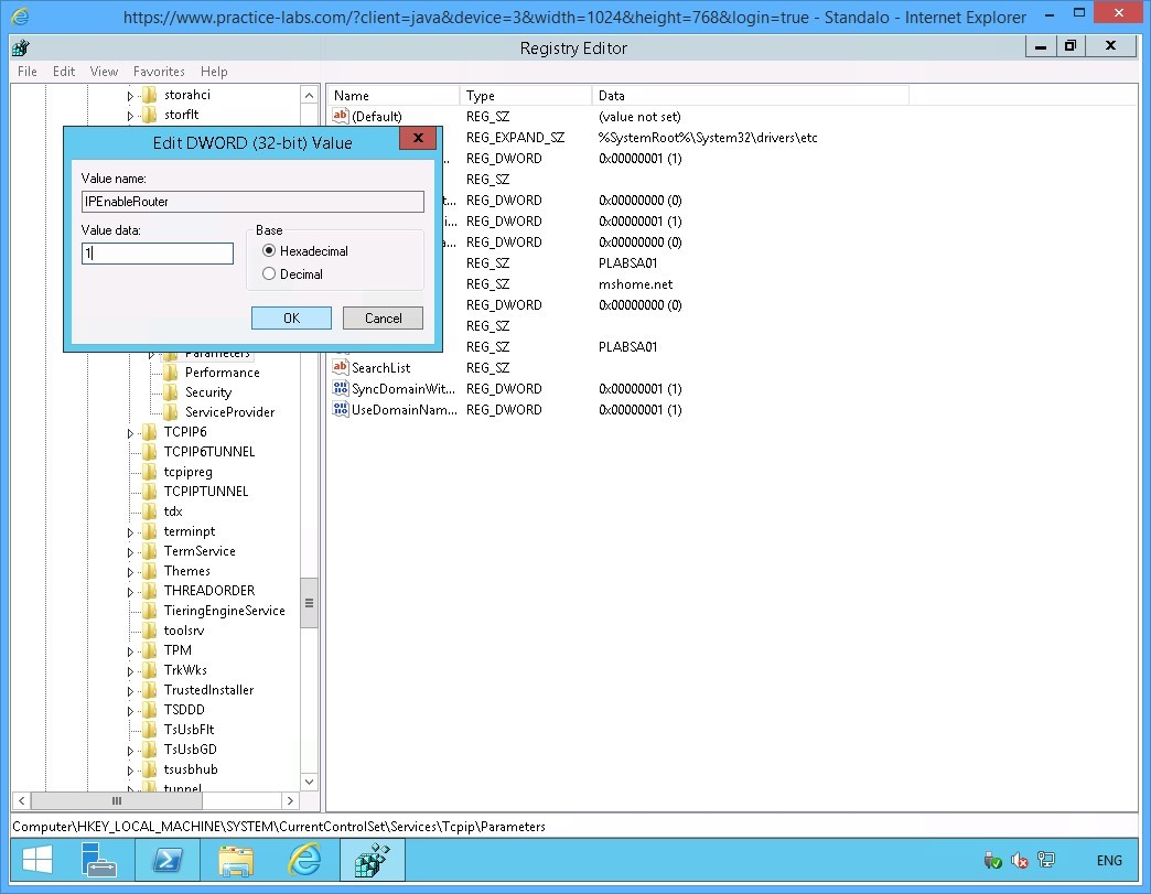
Step 5
On the Edit DWORD (32-bit) Value dialog box, click in the Value data text box and type:
1
Click OK.
Close Registry Editor.
Step 6
You are navigated back to the Windows PowerShell window.
On the PowerShell prompt, type:
Shutdown /r /t 0
Press Enter.
Note: You need to restart PLABSA01 after enabling the IPRouter. This will allow IP routing capability on PLABSA01 to be initialized.

Step 7
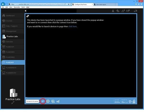
On your computer, go back to Practice Labs web application.
After about a minute, reconnect to PLABSA01 device.
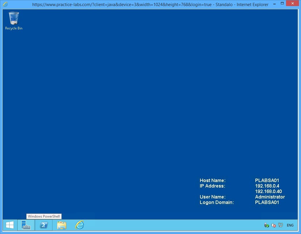
Step 8
Click the Windows PowerShell icon on task bar to display the Windows PowerShell window.
Step 9
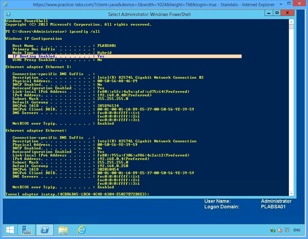
On the PowerShell prompt, type:
Ipconfig /all
Press Enter.
Step 10
From the IP configuration displayed, notice the following value:
IP Routing Enabled = Yes
This verifies that IP routing is now enables on PLABSA01.
Leave the Windows PowerShell window open.
Keep all devices powered on in their current state and proceed to the next task.
Task 5 - Disable IPv6 on the Domain Server
In this task, you will disable IPv6 network protocol on PLABDM01.
To disable IPv6 on the domain server, perform the following steps:
Step 1
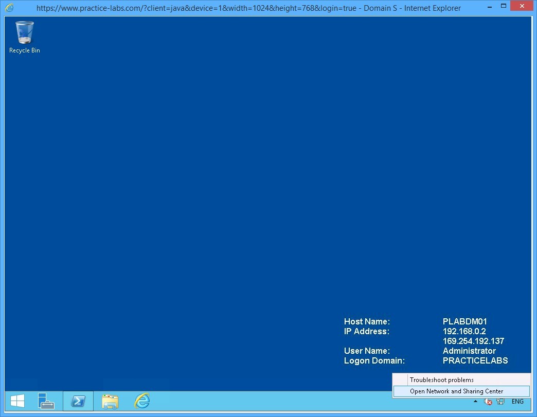
Connect to PLABDM01.
Right-click the network icon on the system tray and select Open Network and Sharing Centre.
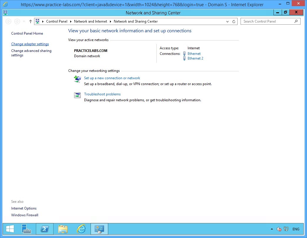
Step 2
On Network and Sharing Center, click Change adapter settings from the left pane.
Step 3
On the Network Connections window, right-click Ethernet 2 and select Properties.
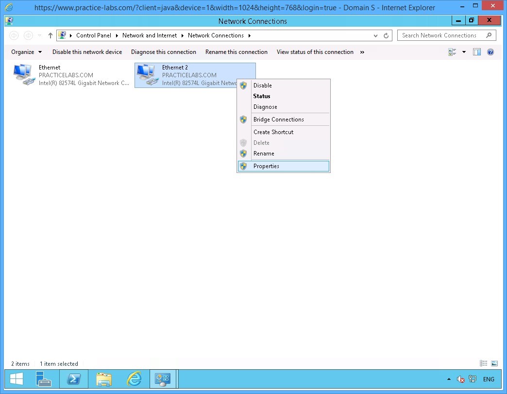
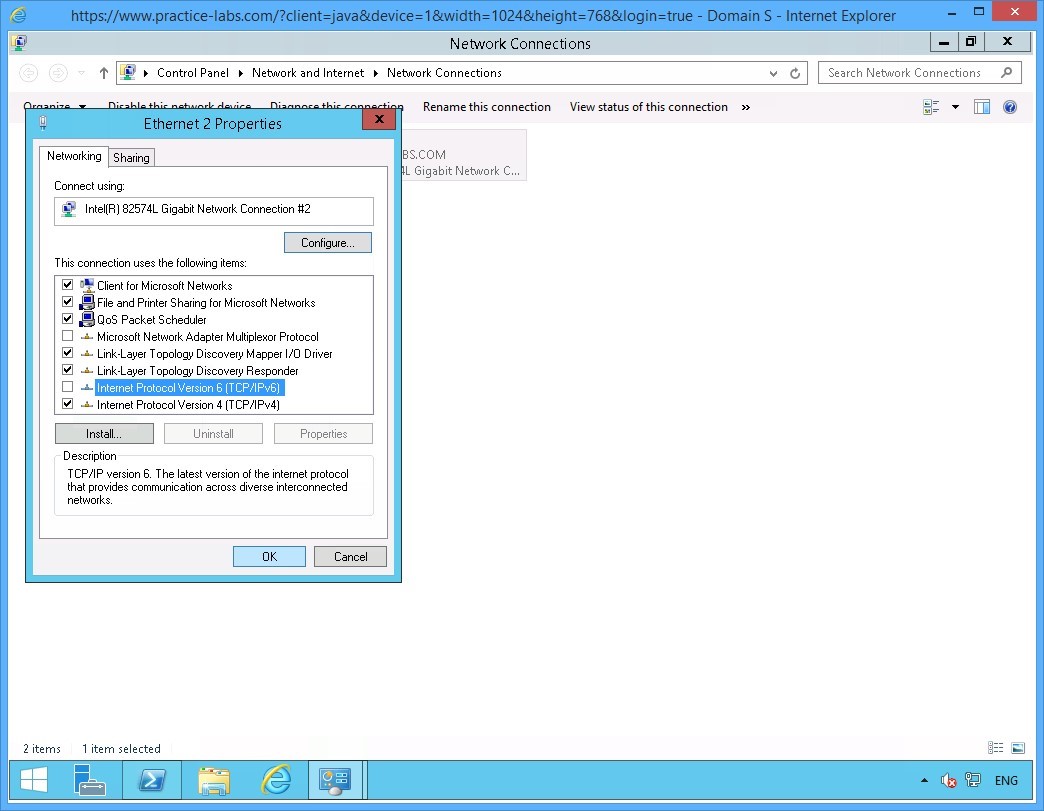
Step 4
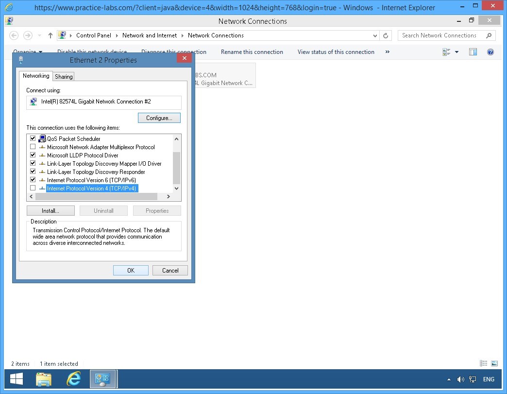
On the Ethernet 2 Properties dialog box, clear the Internet Protocol Version 6 (TCP/IPv6) check box.
Click OK.
Close all the open windows.
Keep all devices powered on in their current state and proceed to the next task.
Task 6 - Disable IPv4 on Windows 8.1
In this task, you will disable the operations of IPv4 on PLABWIN810.
To disable IPv4 network protocol, perform the following steps:
Step 1
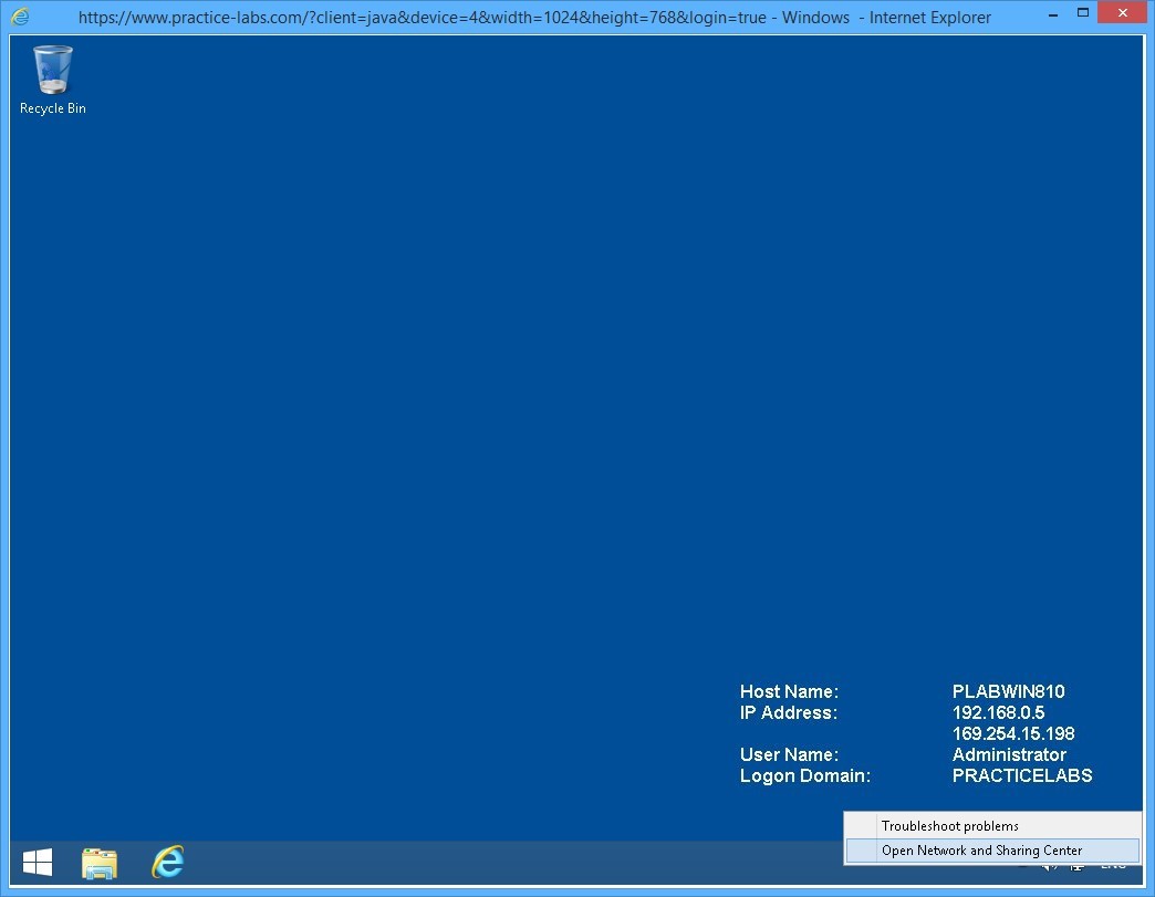
Switch to PLABWIN810 device.
Right-click network icon on the system tray and select Open Network and Sharing Center.
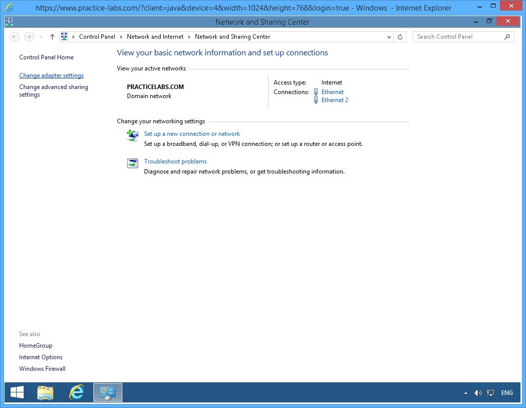
Step 2
On the Network and Sharing Center window, click Change adapter settings on the left pane.
Step 3
On the Network Connections window, right-click Ethernet 2 and select Properties.
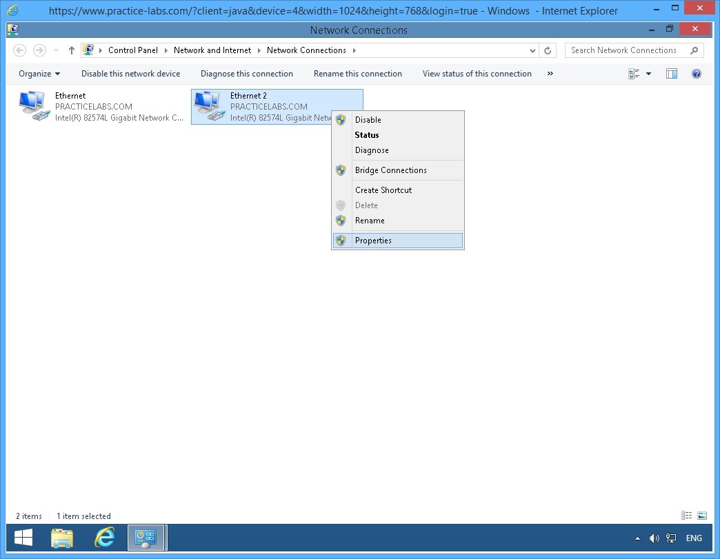
Step 4
On the Ethernet 2 Properties dialog box, scroll down and clear the Internet Protocol Version 4 (TCP/IPv4) box.
Click OK.
Close all the open windows to reach the desktop.
Keep all devices powered on in their current state and proceed to the next task.
Task 7 - Verify the IP Address of IPv6 on the Second Interface PLABWIN810
After disabling the IPv4 on Windows 8.1 workstation, you need to verify that an IPv6 address on this computer is automatically generated.
To verify the IPv6 address on the second interface of PLABWIN810, perform the following steps:
Step 1
From PLABWIN810 device, click the Start charm to access the Start screen.

Step 2
On the Windows Start screen, type:
PowerShell
Press Enter.
Step 3
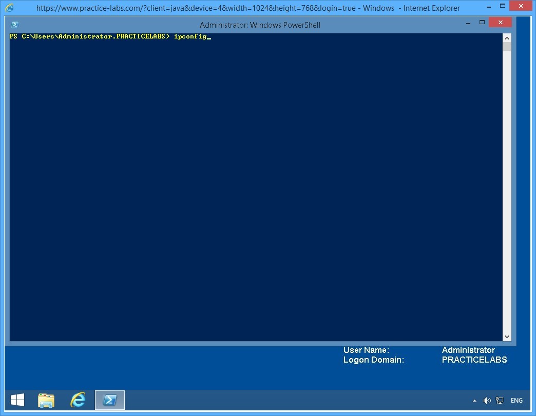
The Windows PowerShell window is displayed.
Then type:
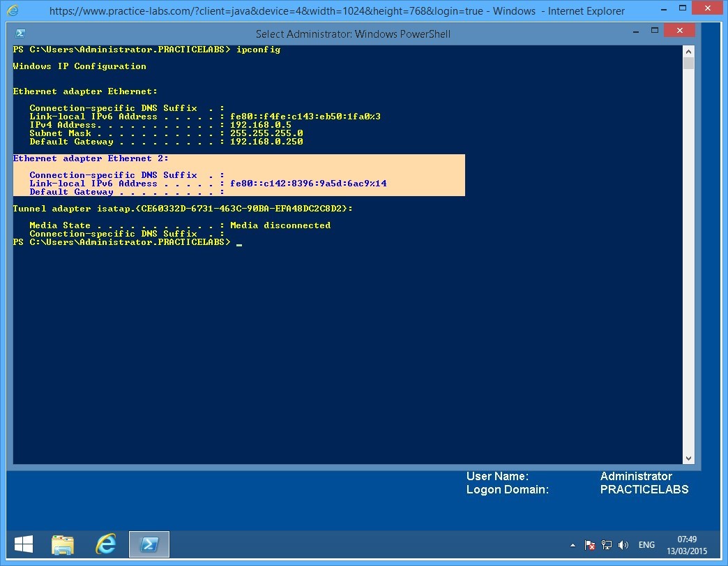
Ipconfig
Press Enter.
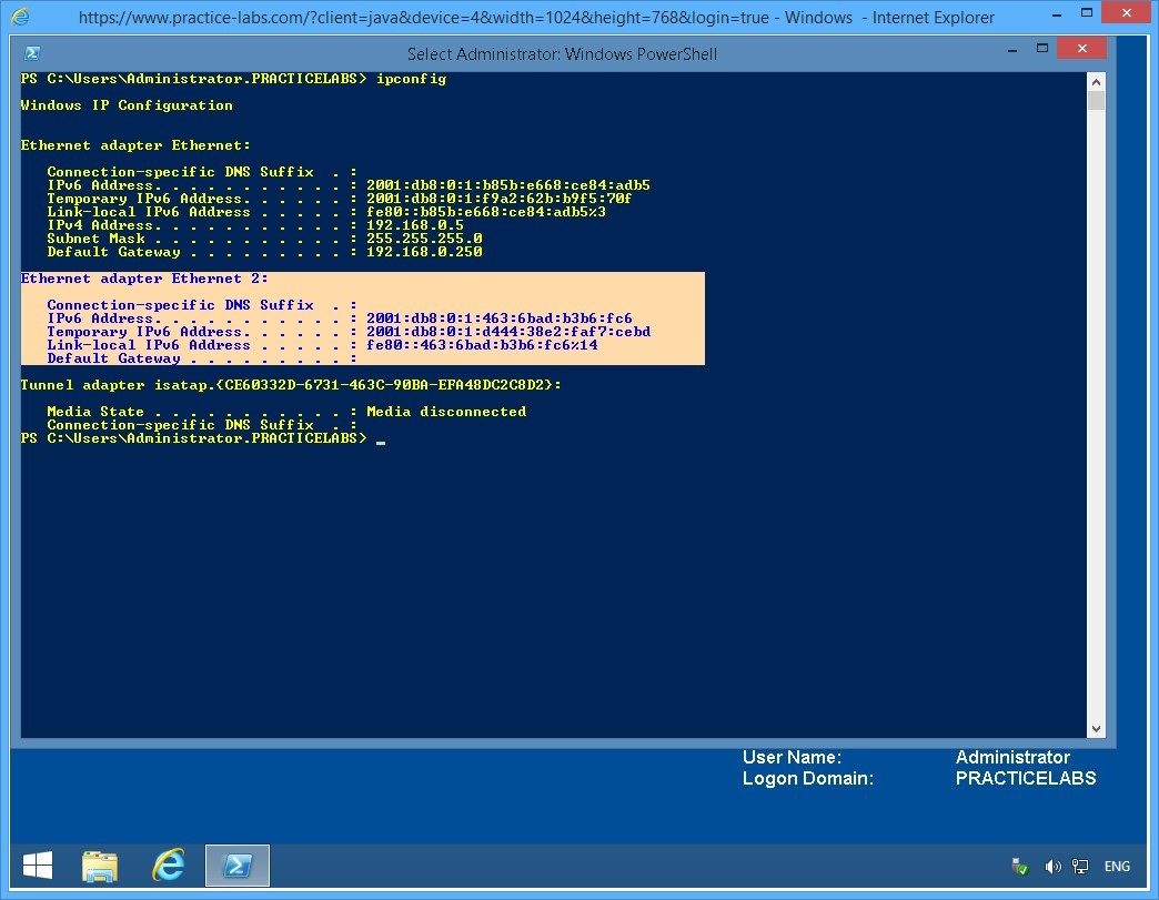
Step 4
From the IP configuration displayed, you will notice that only IPv6 is running on Ethernet 2 and is using an automatically generated IP address beginning with fe80.
Keep the Windows PowerShell window open.
Note: In TCP/IPv6, an IP address starting with fe80 is similar to TCP/IPv4’s automatic private IP address (APIPA) that begins with 169.254.x.x
Keep all devices powered on in their current state and proceed to the next task.
Task 8 - Configure an IPv6 Router Advertisement for Global Address 2001: on the PLABSA01
In this task, you will configure PLABSA01 to advertise itself as the ISATAP router. This enables the ISATAP devices to find the router, to connect to it, and to get the addressing and routing information required to set up an ISATAP connection.
To configure and IPv6 router advertisement on PLABSA01, perform the following steps:
Step 1
Switch over to PLABSA01.
From the PowerShell prompt, type the following command:
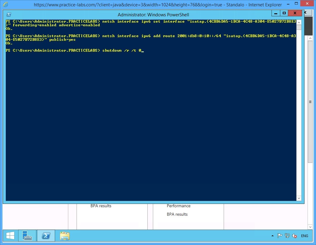
netsh interface ipv6 set interface "Ethernet 2" forwarding=enabled advertise=enabled
Press Enter.
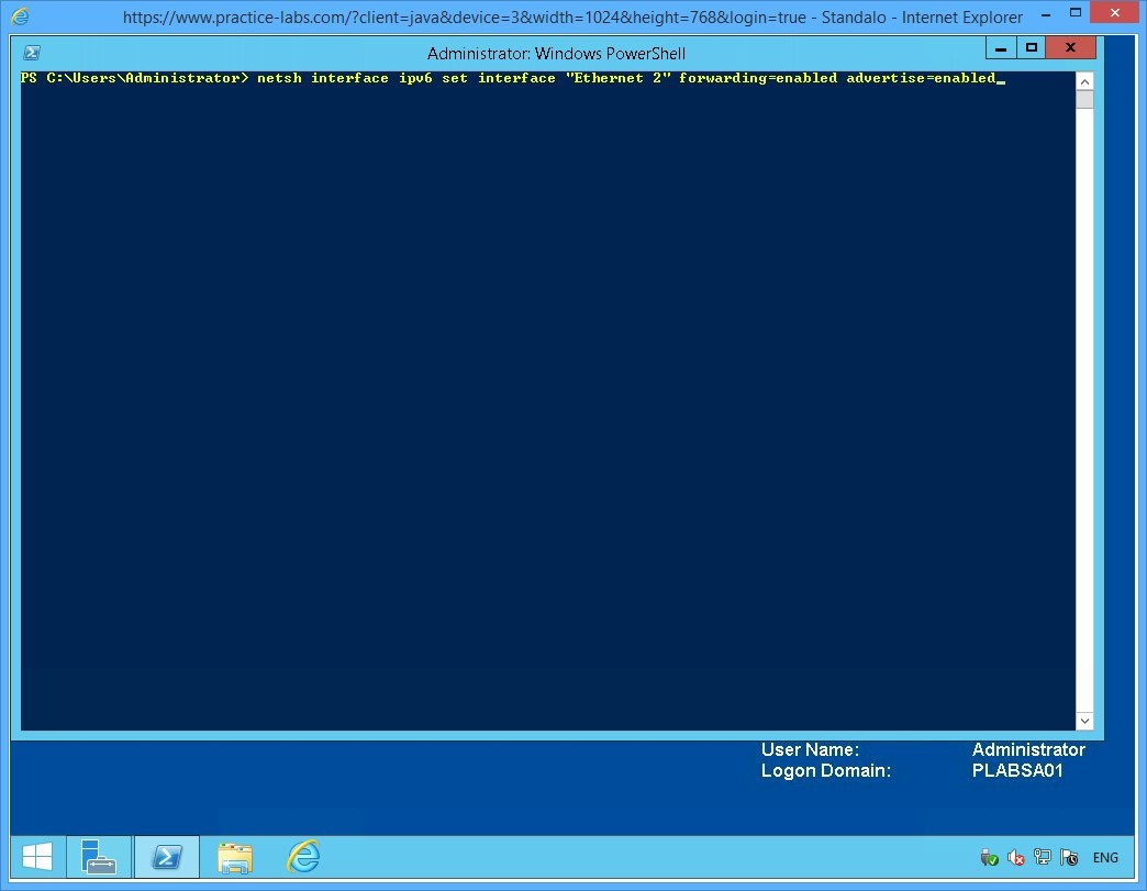
Step 2
Notice that the system responds to the command with an OK. This confirms that the advertising is now enabled.
On the next PowerShell prompt, type the following command:
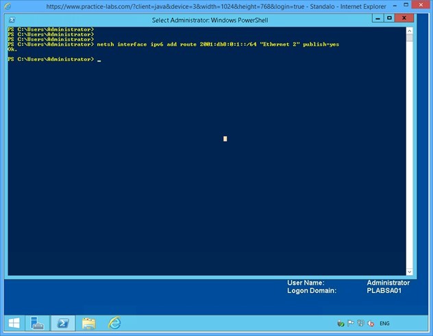
netsh interface ipv6 add route 2001:db8:0:1::/64 "Ethernet 2" publish=yes
Press Enter.
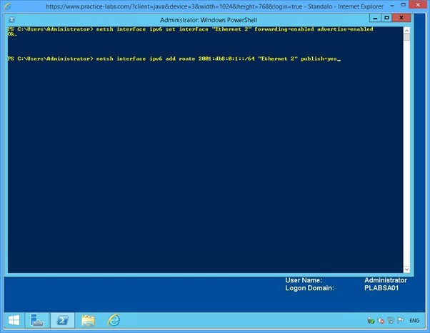
Step 3
Notice the OK response again. This response confirms that the ISATAP routing address is now configured as 2001.
Close the Windows PowerShell window.
Keep all devices powered on in their current state and proceed to the next task.
Task 9 - Verify IPv6 Configuration on PLABWIN810
After setting up the ISATAP router, you need to verify that the router is advertising its presence as configured. In addition, you verify that the router is able to provide the addressing and the routing inputs required for setting up the connection between IPv6-only devices and the IPv4-only devices.
In this task, you will verify that PLABWIN810, which is now an IPv6-only device, is receiving the 2001 routing address to enable it to connect to the other IPv4-only devices on the network.
To verify IPv6 configuration on PLABWIN810, perform the following steps:
Step 1
Switch to PLABWIN810 and go back to PowerShell prompt.
On the command prompt, type:
ipconfig
Press Enter.
Step 2
From the configuration details displayed, notice that IPv6 on the Ethernet 2 interface is bound to a global address compatible with 2001:db8:0:1: format.
Minimize PowerShell window.
Leave the devices you have powered on in their current state and proceed to the next exercise.
Exercise 2 - Setup Network Connectivity between IPv4 and IPv6 devices
With the environment configured in exercise 1 to support an ISATAP router, you will now setup network communication session amongst IPv4-only network and IPv6-only network.
To better understand this technology, refer also to your course material or use your preferred search engine to research this topic in detail.
Task 1 - Add the PLABSA01 to the PRACTICELABS.COM domain
You need to make PLABSA01 a member server of the PRACTICELABS.COM domain, to allow the ISATAP enabled devices to contact the router on the server for the addressing and routing details.
To add the PLABSA01 to the domain, perform the following tasks:
Step 1
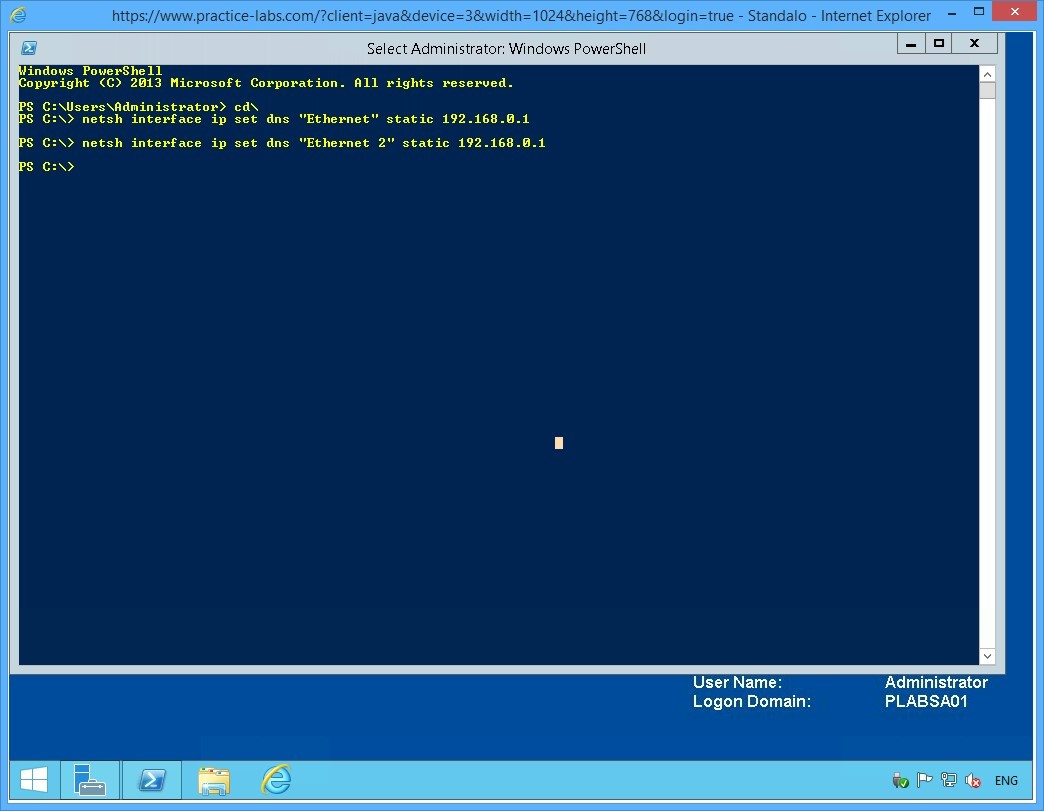
On PLABSA01, reopen the Windows PowerShell window and type the following commands one-by-one. Press Enter after every command.
cd\
netsh interface ip set dns "Ethernet" static 192.168.0.1
netsh interface ip set dns "Ethernet 2" static 192.168.0.1
Note: If prompted with the message: “The configured DNS server is incorrect or does not exist.” Ignore the message and repeat the same command. This is caused by network delays where PLABSA01 cannot reach PLABDC01 immediately.
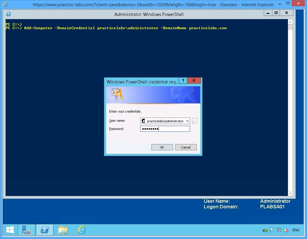
Step 2
On the next PowerShell prompt, type:
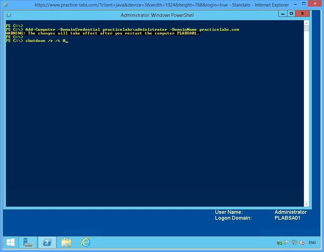
Add-Computer -DomainCredential practicelabs\administrator -DomainName practicelabs.com
Press Enter.

Step 3
When asked for password, type:
Passw0rd
Click OK.
Step 4
Notice the warning to restart the computer.
On the next command prompt, type:
Shutdown /r /t 0
Press Enter.
Keep all devices powered on in their current state and proceed to the next task.
Task 2 - Add Host Records of PLABSA01 in DNS Server
In this task, you will add a host record of the PLABSA01 on DNS Server service in PLABDC01.
To add a host record of PLABSA01, perform the following tasks:
Step 1
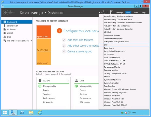
Switch to PLABDC01.
On the Server Manager window displayed, click Tools from the menu on the top and then select DNS.
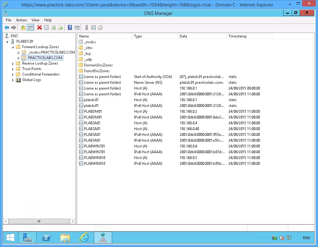
Step 2
On the DNS Manager, expand the PLABDC01 node under the console tree on the left pane.
Under the PLABDC01 node, expand the Forward Lookup Zones node and then expand PRACTICELABS.COM
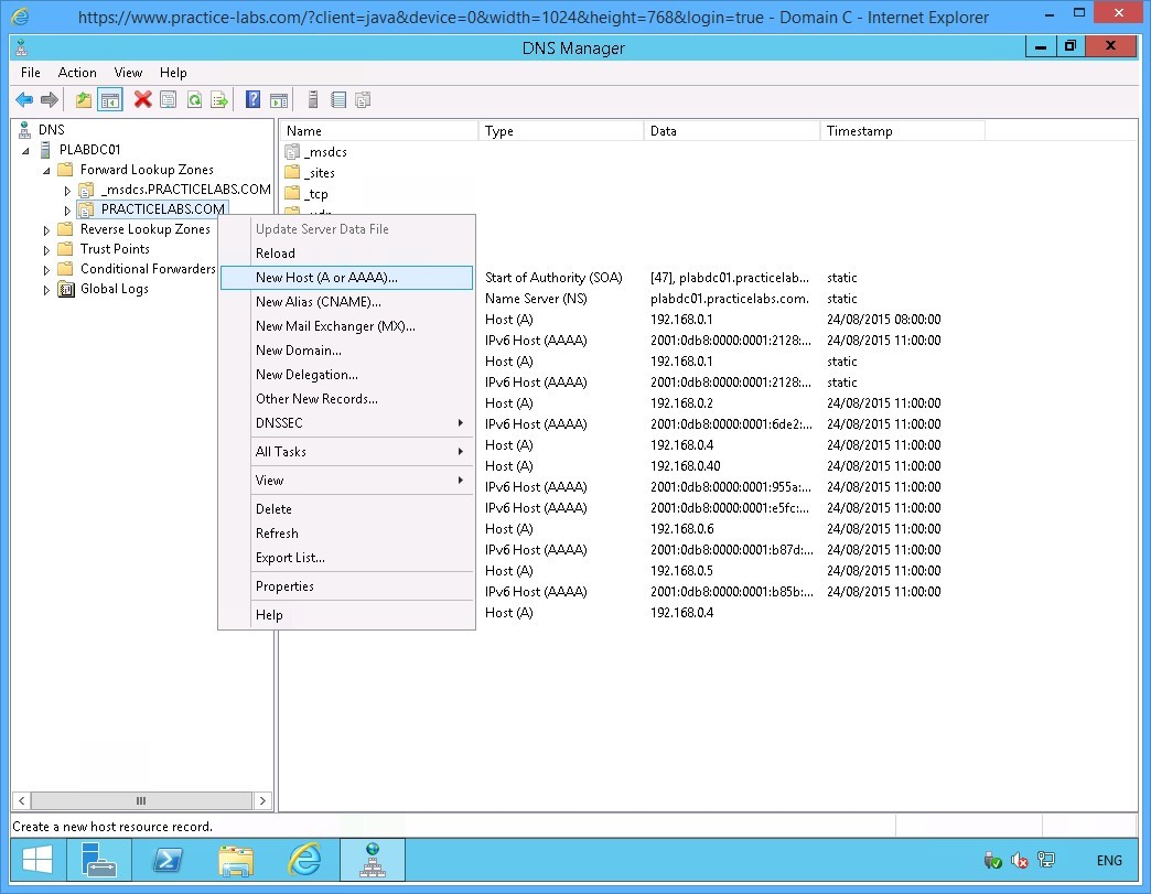
Step 3
Right-click PRACTICELABS.COM and select New Host (A or AAAA).
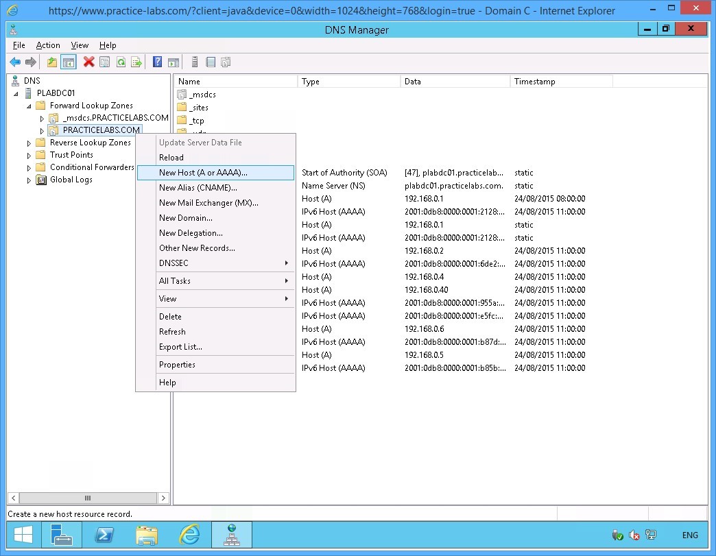
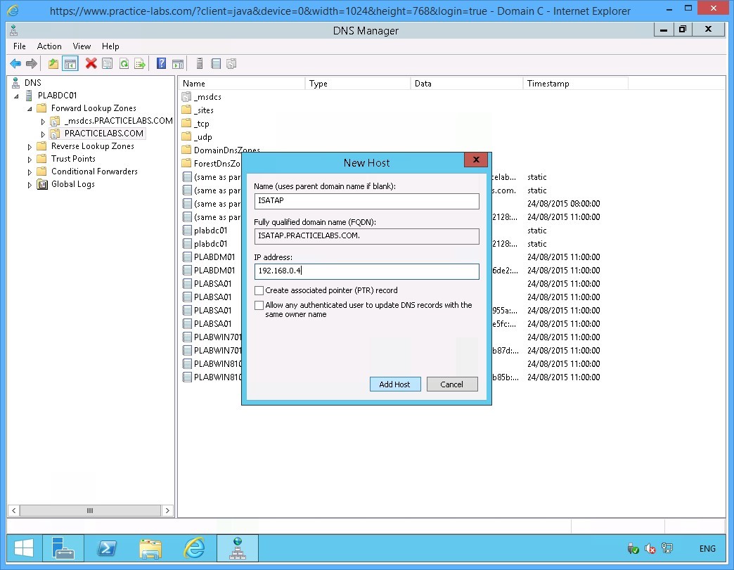
Step 4
In the New Host dialog box, specify the following values:
Name (uses parent domain name if blank): ISATAP
IP address: 192.168.0.4
Click Add Host.
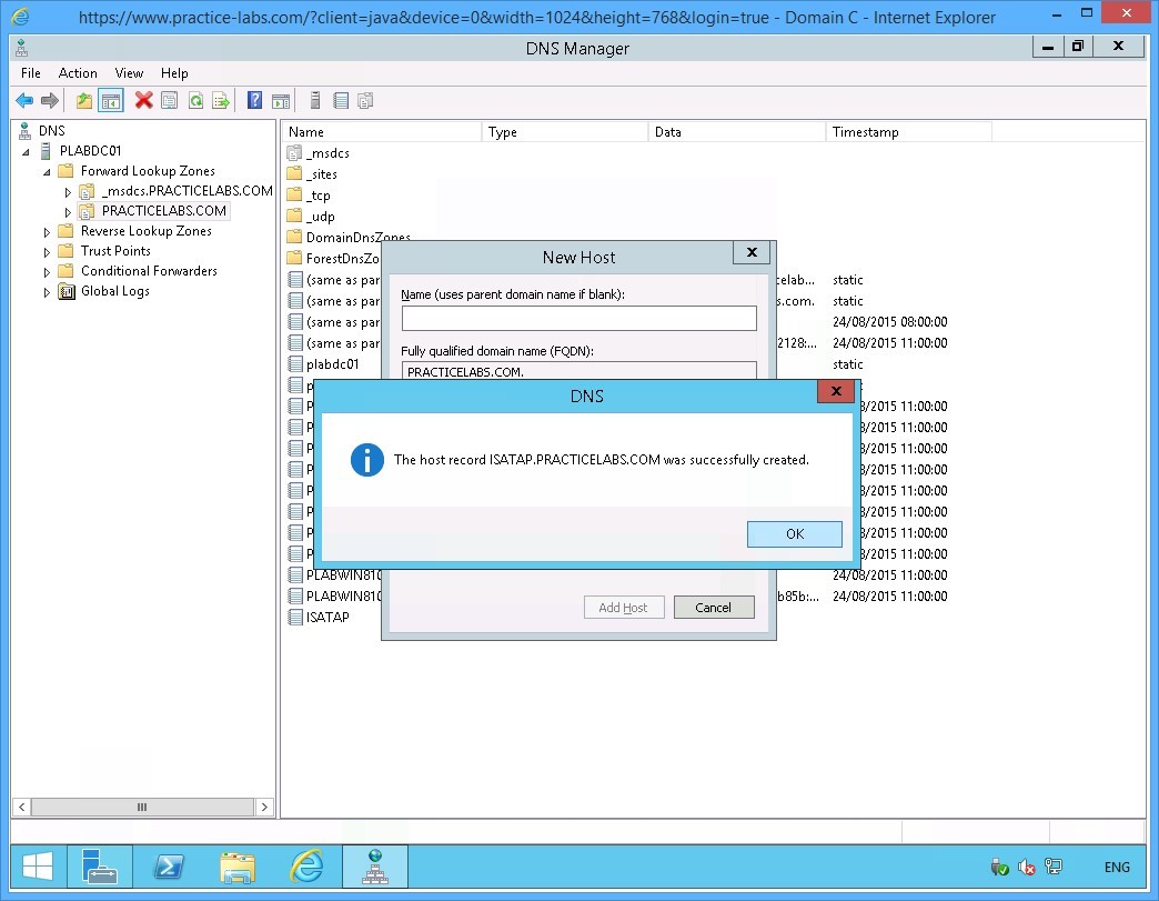
Step 5
The DNS dialog box appears informing that the record was setup successfully.
Click OK to close the dialog box.
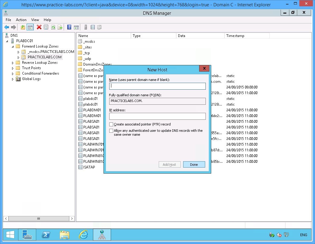
Step 6
Click Done.
Step 7
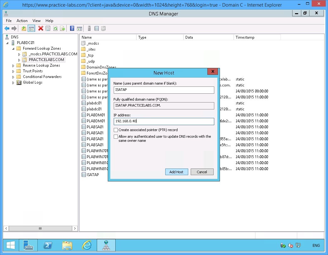
Right-click again on PRACTICELABS.COM and select New Host (A or AAAA)….
Step 8
On the New Host dialog box, specify the following values:
Name (uses parent domain name if blank): ISATAP
IP address: 192.168.0.40
Click Add Host.
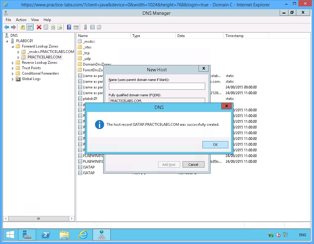
Step 9
The DNS dialog box appears informing that the record was setup successfully.
Click OK to close the dialog box.
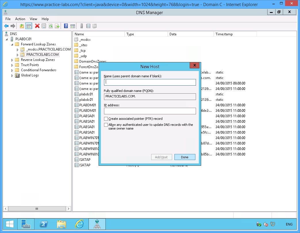
Step 10
You are back in the New Host dialog box.
Click Done to close the dialog box.
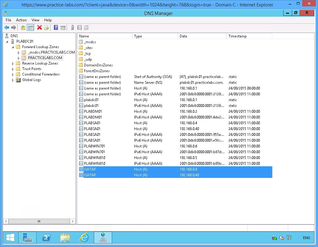
Step 11
Find the two new Host (A) records that you just added.
Close DNS Manager Application window.
Keep all devices powered on in their current state and proceed to the next task.
Task 3 - Configure ISATAP router on PLABSA01
You will use NETSH commands to configure a server as an ISATAP router. In this task, you will configure an ISATAP router on the PLABSA01 server.
To configure an ISATAP router on the stand-alone server, perform the following steps:
Step 1
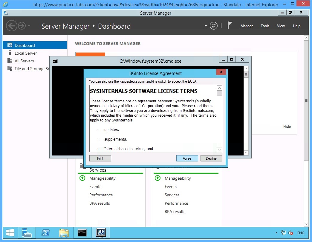
Connect to PLABSA01 device after the restart that you initiated earlier.
On the BGInfo License Agreement dialog box, click Agree to close the dialog box.
Step 2
Click the Windows PowerShell icon on the task bar.
Step 3
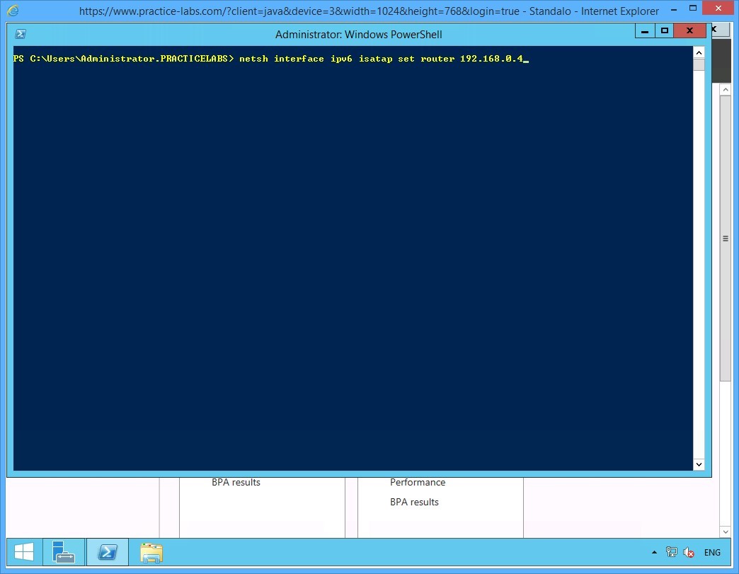
On the PowerShell prompt, type:
Netsh interface ipv6 isatap set router 192.168.0.4
Press Enter.
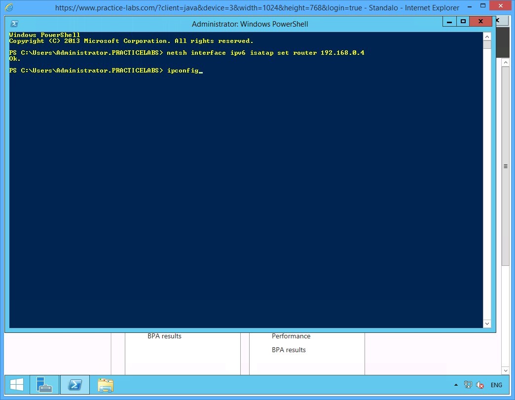
Step 4
Notice the system responds with an OK to confirm the ISATAP router has been setup on the server.
On the next PowerShell prompt, type:
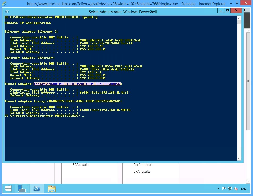
ipconfig
Press Enter.
Step 5
On the configuration details displayed, notice the details of the two tunnel adapters configured for ISATAP.
Note down the value of the isatap.{interface_index} of the first tunnel adapter.
Important: You can use click and drag your mouse to select the value of the isatap.{interface_index} of the first tunnel adapter.
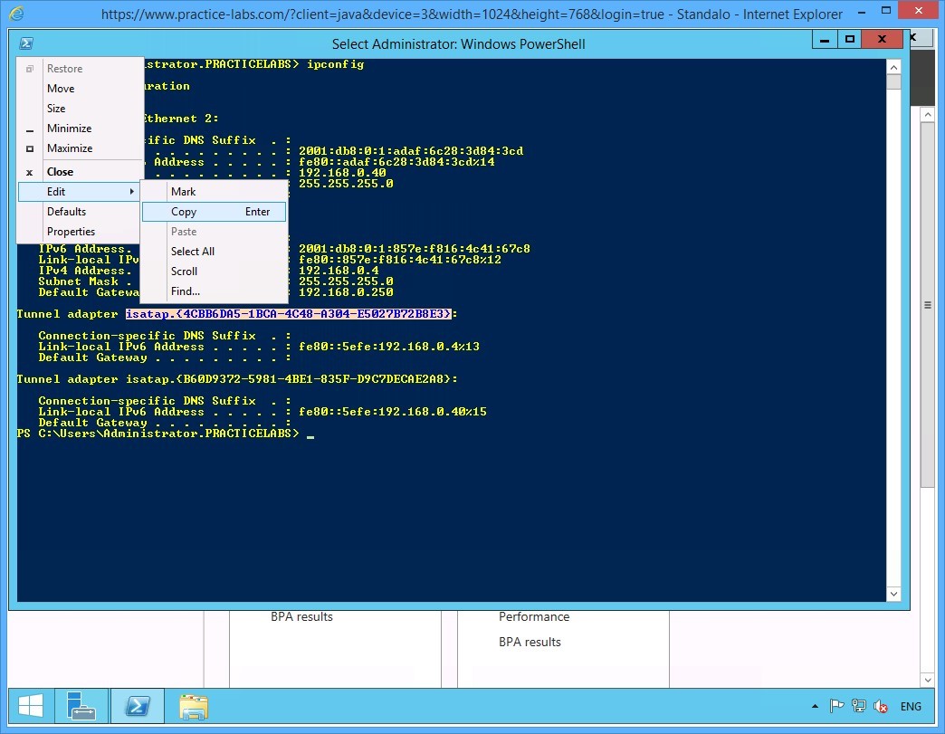
Step 6
Click on the PowerShell icon on the top left.
Go to Edit and choose Copy.
Step 7
On the next PowerShell prompt, type the following command:
Netsh interface ipv6 set interface "isatap.Interface_Index" forwarding=enabled advertise=enabled
Note: In this command, replace interface index with the alpha-numeric value of the interface index you copied or noted down from the previous step. Remember to include the curly brackets, as per the command format. You can use the command prompt’s Copy and Paste function as well.
Press Enter.
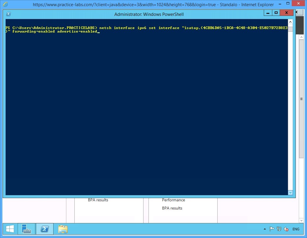
Step 8
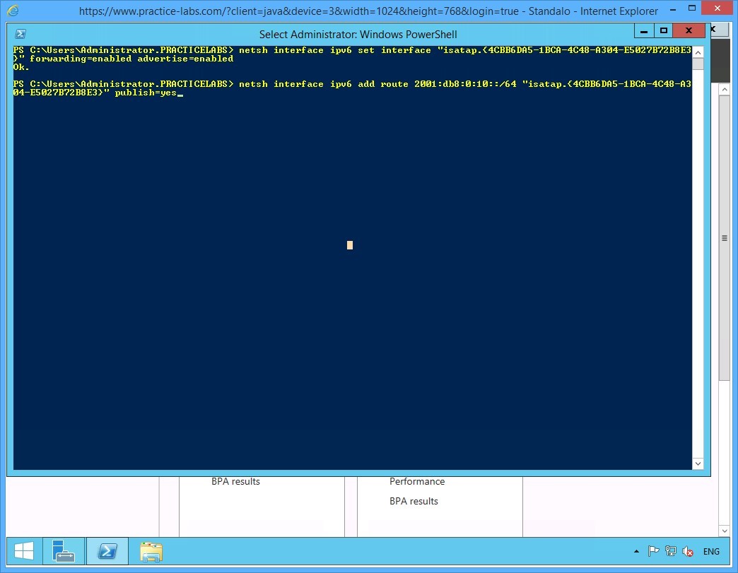
Notice that the system responds to the command with OK, confirming that the ISATAP addressing information is now configured on the PLABSA01 ISATAP router.
On the next PowerShell prompt, type:
Netsh interface ipv6 add route 2001:db8:0:10::/64 "isatap.{interface_index}" publish=yes
Note: In this command, replace interface index with the alpha-numeric value of the interface index noted down from one of the earlier steps. Remember to include the curly brackets, as per the command format. You can use the command prompt’s Copy and Paste function as well.
Press Enter.
Step 9
To enable the configuration to take effect, restart PLABSA01 by typing:
Shutdown /r /t 0
Press Enter.
Step 10
After about a minute, reconnect to PLABSA01 device.
Click Windows PowerShell on taskbar and then type:
ipconfig
Press Enter.
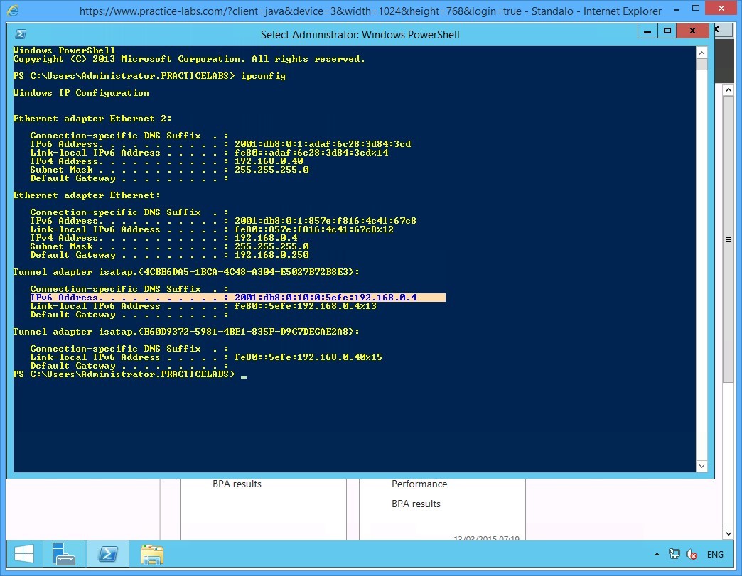
Step 11
From the details displayed, notice value:
IPv6 Address: 2001:db8:0:10:0:efe:192.168.0.4
This indicates that the IPv4 address 192.168.0.4 is now associated with a global IPv6 address 2001:db8:0:10:0:5efe. This means that ISATAP is setup; and the IPv6-only devices are now able to connect to IPv4-only devices using the global address and routing information.
Please note that the actual value you will get in your lab may slightly differ from the given screen shot below.
Keep all devices powered on in their current state and proceed to the next task.
Task 4 - Enable ISATAP on an IPv4-only Domain Server
After setting up PLABSA01 as an ISATAP router, you enable the IPv4-only domain server to access the ISATAP router. In this task, you will enable PLABDM01 to connect to the ISATAP router PLABSA01.
To enable ISATAP on an IPv4-only domain server, perform the following steps:
Step 1
Switch to PLABDM01.
Launch the Windows PowerShell window and type the following commands one-by-one. Press Enter at the end of each command.
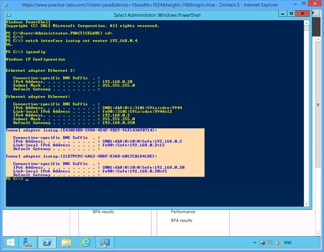
cd\
netsh interface isatap set router 192.168.0.4

Step 2
Notice that the system responds to the command with an OK. This confirms that PLABDM01 is now ISATAP enabled.
On the next PowerShell prompt, type:
ipconfig
Press Enter.

Step 3
From the results displayed, notice that:
1) The alpha-numeric values of the isatap. {interface_index} for the Tunnel adapter on this server is the same as was noted on PLABSA01 - an ISATAP router. This confirms that the ISATAP router is providing the addressing information to the ISATAP-enabled server.
2) The IPv6 address for PLABDM01 is from the global series 2001:db8:0:10:0:5efe and is associated with the IPv4 address 192.168.0.2
Therefore, the ISATAP router - PLABSA01 - is providing the required addressing and routing information to the IPv4-only PLABDM01.
Close the Windows PowerShell window.
Keep all devices powered on in their current state and proceed to the next task.
Task 5 - Set Firewall Rules to Enable Network Connectivity
To allow network communication between PLABDM01 and PLABWIN810, set firewall rules to enable the connection. In this task, you will enable the File and Printer Sharing service on PLABDM01. This enables the server to respond to ping requests.
To set firewall rules to enable connection, perform the following steps:
Step 1
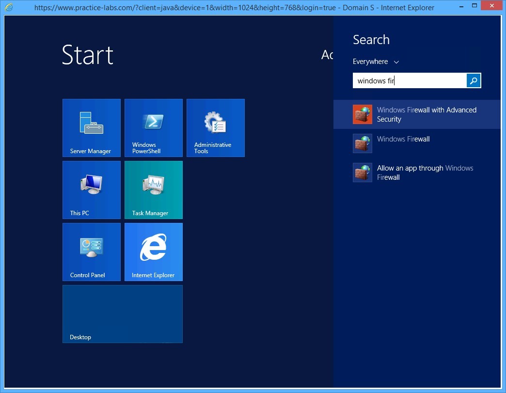
On PLABDM01, click Start charm to open the Start screen.
Step 2
On the Start screen, type windows firewall with advanced security and press Enter.
Step 3
On the Windows Firewall with Advanced Security window, click Inbound Rules in the left pane of the console tree. List of Inbound Rules is displayed in the middle pane.
Scroll down and then right-click File and Printer Sharing (Echo Request - ICMPv4-In) and select Enable Rule.
If the above rule has green tick appended to it, go to the next step.
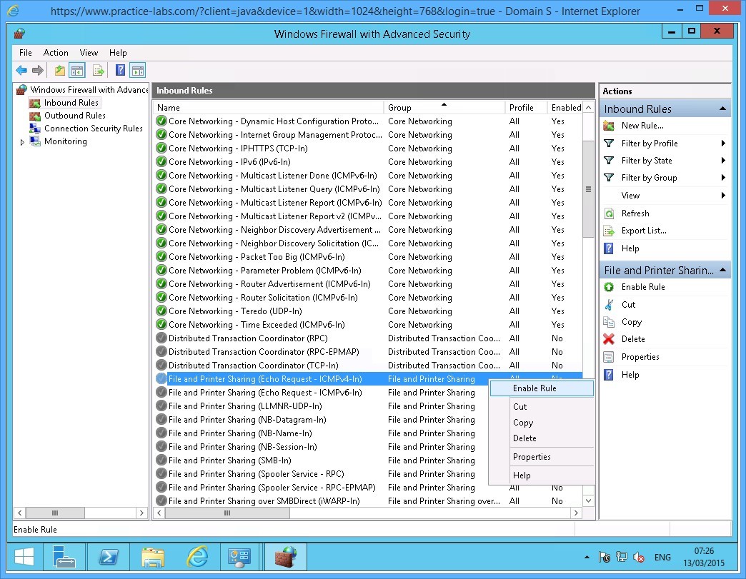
Step 4
Right-click File and Printer Sharing (Echo Request - ICMPv6-In) and select Enable Rule.
If the above rule has green tick appended to it or is already Enabled, go to the next step.

Keep all devices powered on in their current state and proceed to the next task.
Task 6 - Verify Connectivity between IPv4-only and IPv6-only Devices on the Network
Now that the network is configured for ISATAP connection, the IPv6-only PLABWIN810 can communicate with the IPv4-only PLABDM01. To verify that the connection is working, by sending ping packets.
In this task, you ping PLABDM01 from PLABWIN810 to verify that they can communicate with each other using the ISATAP configuration on PLABSA01.
To verify connectivity among IPv4-only and IPv6-only devices on the network, perform the following steps:
Step 1
Switch to PLABWIN810.
Launch the Windows PowerShell window and type:
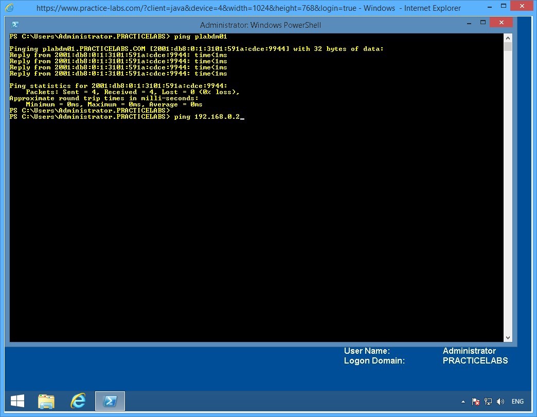
ping plabdm01
Press Enter.
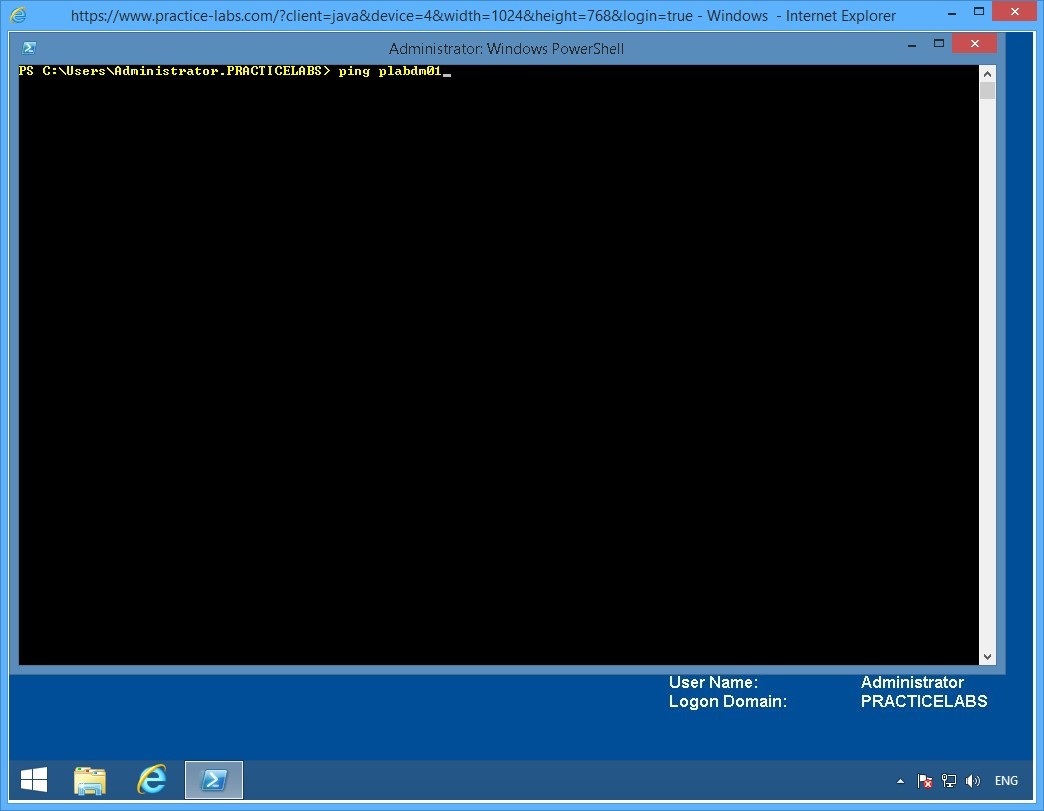
Step 2
Notice that PLABDM01 responds. Moreover, the response is from the global IPv6 address provided by the isatap router.
On the next PowerShell prompt, type:
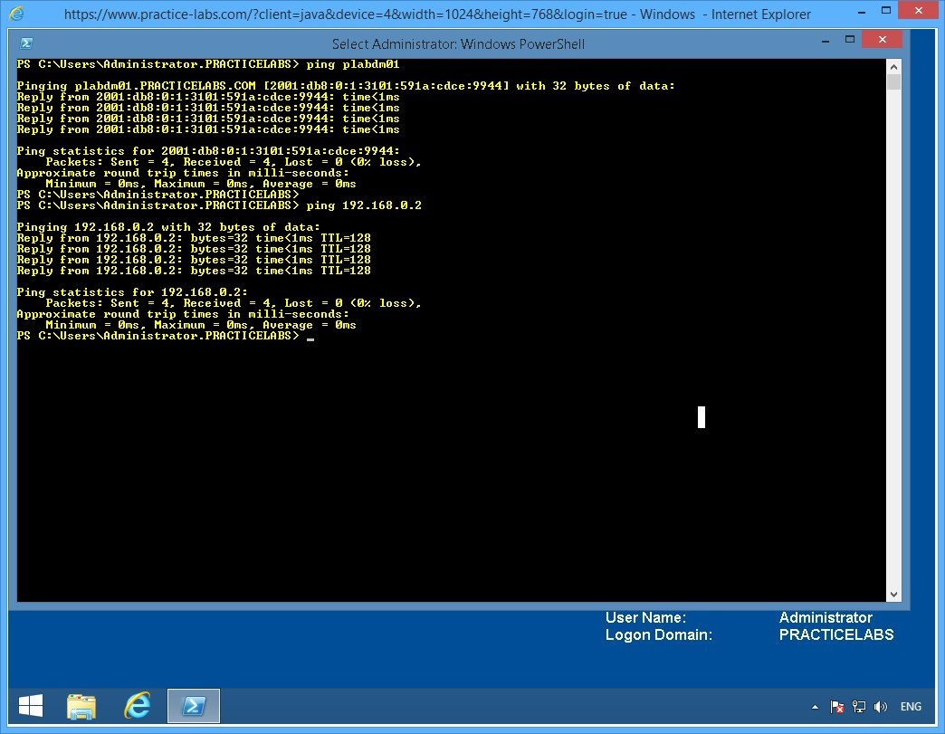
ping 192.168.0.2
Press Enter.
This command pings the IPv4 service on PLABDM01.
Step 3
Notice that IPv4 responds to the ping.
A new set of lab devices will be assigned to you for the next exercise. Please note that all changes you have made in the previous exercise will be discarded. The devices will be rolled back to their default settings.
Exercise 3 - Static Routing
In this exercise you will learn how to configure static routes and compare them with dynamic routes in a routed network. Please refer to your course material or use your favourite search engine to read up on the following topics:
- Static routes in Microsoft Windows
- Configuring Static routes using Cisco routers
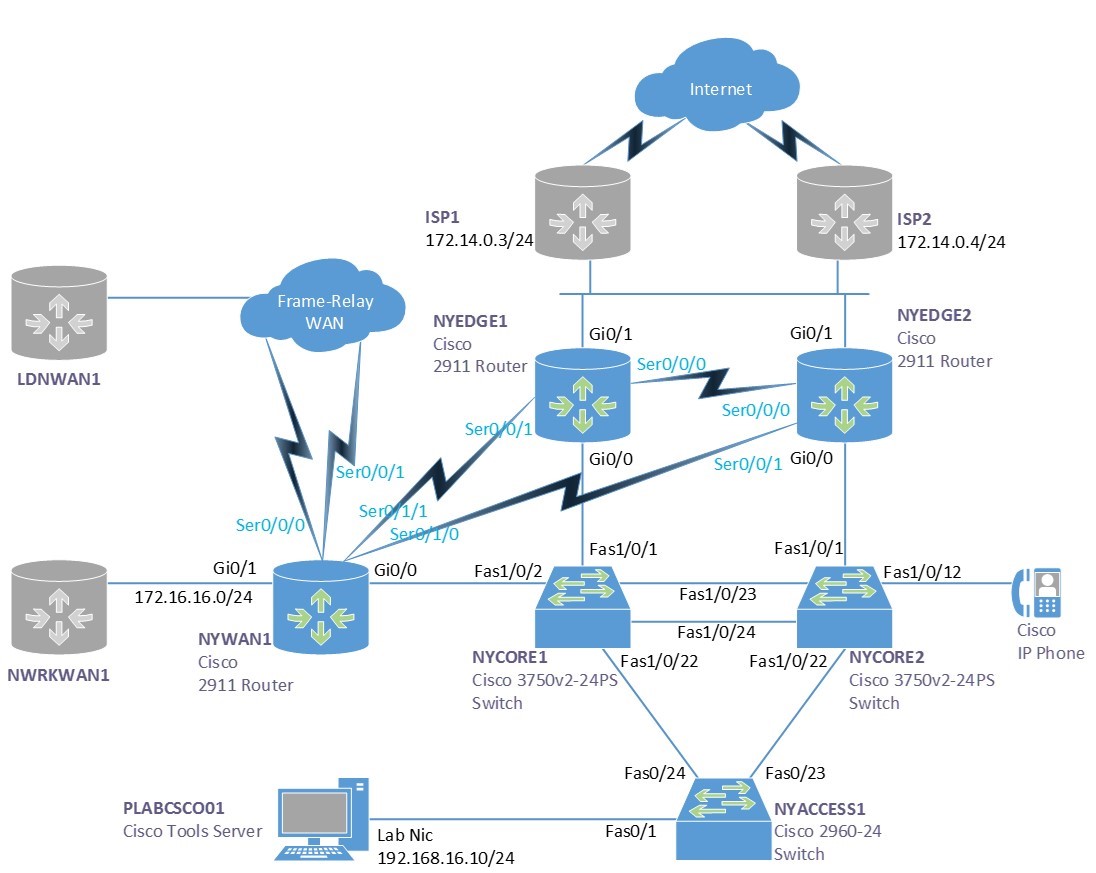
Lab Diagram
During your session you will have access to the following lab configuration. Depending on the exercises you may or may not use all of the devices, but they are shown here in the layout to get an overall understanding of the topology of the lab.
Connecting to your Lab
In this module you will be working on the following equipment to carry out the steps defined in each exercise.
- NYEDGE1 (Cisco Router)
- NYWAN1 (Cisco Router)
- PLABCSCO01 (Windows PC - Cisco Tools Server)
Task 1 - Viewing the routing table
A routing table on a router or pc/server is a list of networks that are known to that device. If a network is unknown then a special address called a default gateway is used, the device will send any traffic too this address if the local routing table does not find a match.
Most servers and PC’s only have a basic routing table including a list of internal network cards and a default gateway. Occasionally you find additional routes on servers or PC’s for special circumstances and in even rarer cases you may even find a routing protocol such as RIP configured.
However most devices rely on an external router called the default gateway to find where to send traffic to.
To view the routing table of both a server and a router, follow these steps:
Step 1
Ensure PLABCSCO01 is powered on, once you are connected to the desktop double click the command prompt icon on the desktop, or navigate to Start > Run and type cmd.
Step 2
To view the routing table of a server you can use the following command:
route print
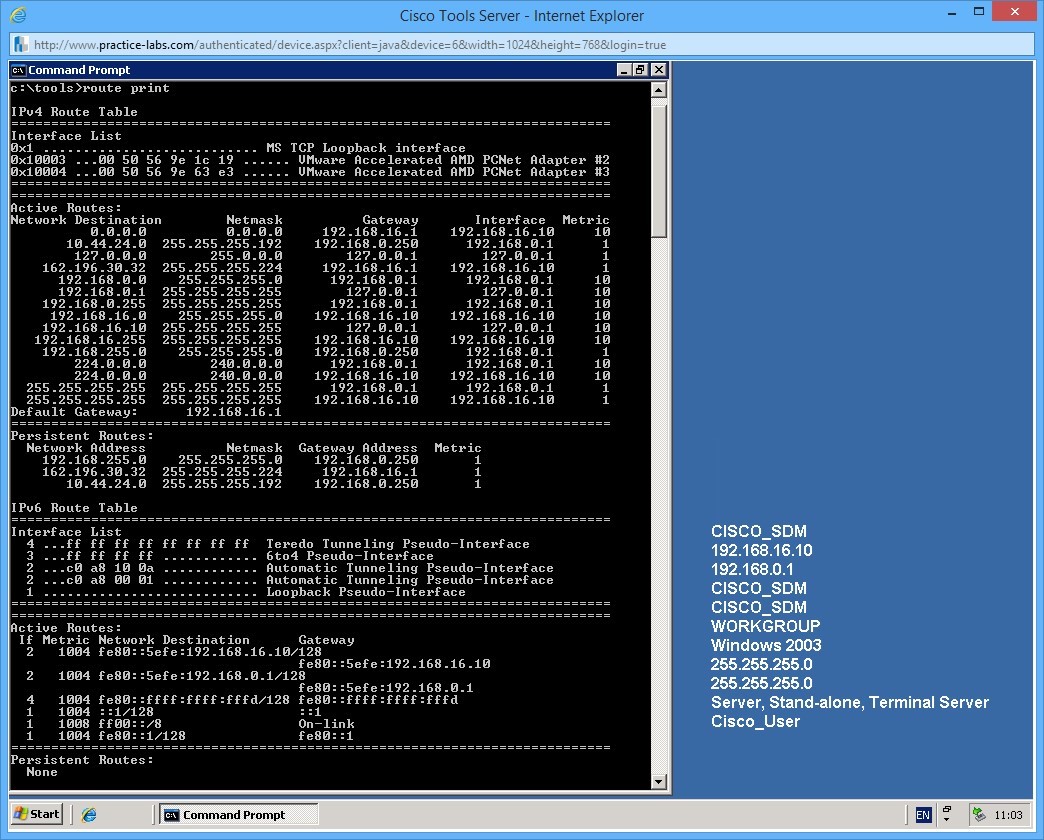
In the output you can see there are a number of routes on the server. Here is a breakdown of some of the important ones:
The default gateway
The address 0.0.0.0 with a netmask of 0.0.0.0 is the default gateway, this will automatically match all IP Addresses, but as the routing table works on a best or longest match preference, it will only match the default gateway address if there are no other preferable matches.
Persistent routes
The persistent routes section in the output shows any routes that have been manually added to the server, these are persistent in that they will survive a reboot of the server. Non-persistent routes will be erased, or forgotten on reboot.
Step 3
Next we will look at the routing table on a router. Here you can imagine it is a little more complex.
Connect to the router NYWAN1 in the lab. When connected, click in the terminal area and press the return/enter key to waken the console port.
If your prompt says NYWAN1> type enable and press return, your prompt should then say NYWAN1#
To view the routing table type:
show ip route
Output from the show ip route command on NYWAN1, use the space bar to page through the results:
NYWAN1#show ip route
Codes: L - local, C - connected, S - static, R - RIP, M - mobile, B - BGP
       D - EIGRP, EX - EIGRP external, O - OSPF, IA - OSPF inter area
       N1 - OSPF NSSA external type 1, N2 - OSPF NSSA external type 2
       E1 - OSPF external type 1, E2 - OSPF external type 2
       i - IS-IS, su - IS-IS summary, L1 - IS-IS level-1, L2 - IS-IS level-2
       ia - IS-IS inter area, * - candidate default, U - per-user static route
       o - ODR, P - periodic downloaded static route, H - NHRP, l - LISP
       + - replicated route, % - next hop override
Gateway of last resort is not set
      10.0.0.0/8 is variably subnetted, 2 subnets, 2 masks
C        10.28.0.0/30 is directly connected, Serial0/0/1.768
L        10.28.0.2/32 is directly connected, Serial0/0/1.768
      172.16.0.0/16 is variably subnetted, 2 subnets, 2 masks
C        172.16.16.0/24 is directly connected, GigabitEthernet0/1
L        172.16.16.1/32 is directly connected, GigabitEthernet0/1
      172.88.0.0/16 is variably subnetted, 7 subnets, 3 masks
D        172.88.0.0/16 is a summary, 00:00:48, Null0
C        172.88.0.0/30 is directly connected, Serial0/0/0.641
L        172.88.0.1/32 is directly connected, Serial0/0/0.641
C        172.88.0.4/30 is directly connected, Serial0/0/1.642
L        172.88.0.5/32 is directly connected, Serial0/0/1.642
C        172.88.0.8/30 is directly connected, Serial0/0/0.256
L        172.88.0.9/32 is directly connected, Serial0/0/0.256
      186.12.0.0/16 is variably subnetted, 2 subnets, 2 masks
C        186.12.0.0/30 is directly connected, Serial0/0/1.512
L        186.12.0.1/32 is directly connected, Serial0/0/1.512            192.168.16.0/24 is variably subnetted, 2 subnets, 2 masks
C        192.168.16.0/24 is directly connected, GigabitEthernet0/0
L        192.168.16.4/32 is directly connected, GigabitEthernet0/0
D     192.168.100.0/24
           [90/28416] via 192.168.16.6, 00:00:36, GigabitEthernet0/0
           [90/28416] via 192.168.16.5, 00:00:36, GigabitEthernet0/0
      192.168.224.0/24 is variably subnetted, 2 subnets, 2 masks
D        192.168.224.0/24
           [90/10639872] via 172.88.0.10, 00:00:44, Serial0/0/0.256
S        192.168.224.1/32 [1/0] via 172.88.0.10
D     192.168.225.0/24
           [90/10639872] via 172.88.0.10, 00:00:44, Serial0/0/0.256
      192.168.226.0/27 is subnetted, 2 subnets
D        192.168.226.0
           [90/10639872] via 172.88.0.10, 00:00:44, Serial0/0/0.256
D        192.168.226.32
           [90/10639872] via 172.88.0.10, 00:00:44, Serial0/0/0.256
Note at the top of the output the key shows what the letters mean on the left hand side next to each route. For example: D means it is an EIGRP, or Enhanced Interior Gateway Routing Protocol, this is a Cisco proprietary routing protocol and is very common in organisations that use Cisco equipment.
Task 2 - Static routes
Static routes are routes that are manually added to the device, you have already seen a number of static routes, there is 1 present in NYWAN1’s routing table, can you find it? And the persistent routes on the Microsoft Server are also static routes as these have been entered in manually.
In this next step you will add a static route to both the router and the Microsoft Server, you will then test your route.
Step 1
In the command prompt that is still open on PLABCSCO01, use the following command to add a persistent static route to the servers routing table:
route add -p 192.168.224.1 mask 255.255.255.255 192.168.16.4
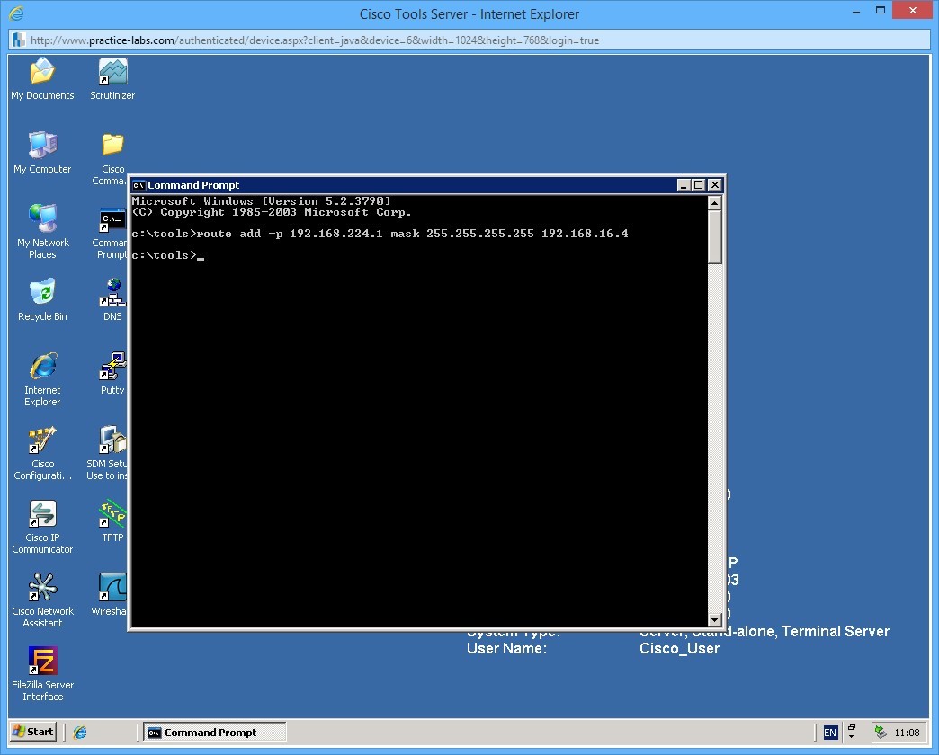
This command adds a route of 192.168.224.1 /32 (255.255.255.255) and tells the server that it should send traffic to the next hop (in this case a router) which has an IP address of 192.168.16.4. The -p switch makes the route persistent.
Once you have added the route, view the routing table again using the command you previously learnt.
Step 2
Next try and add the following non-persistent route:
route add 192.168.227.0 mask 255.255.255.225 192.168.16.1
There are two things wrong with this route, can you work them out?
Step 3
Next we you will add a static route to NYWAN1. This will be the same route that you added to the server, however the next hop will change.
To add the static route, you need to be in global configuration mode. Follow these commands to add the route:
NYWAN1>enable
NYWAN1#configure terminal
Enter configuration commands, one per line.  End with CNTL/Z.
NYWAN1(config)#ip route 192.168.224.1 255.255.255.255 172.88.0.10
In this example the next hop address is 172.88.0.10 which is the other side of a simulated leased line circuit between NYWAN1 and another router.
You can see that maintaining your routing tables using static routes is very cumbersome and even worse prone to human error.
Step 4
Finally let’s confirm that the routes work. There is a device with an IP address of 192.168.224.1 within the subnet of the route you just added. From the server, try and ping this address:
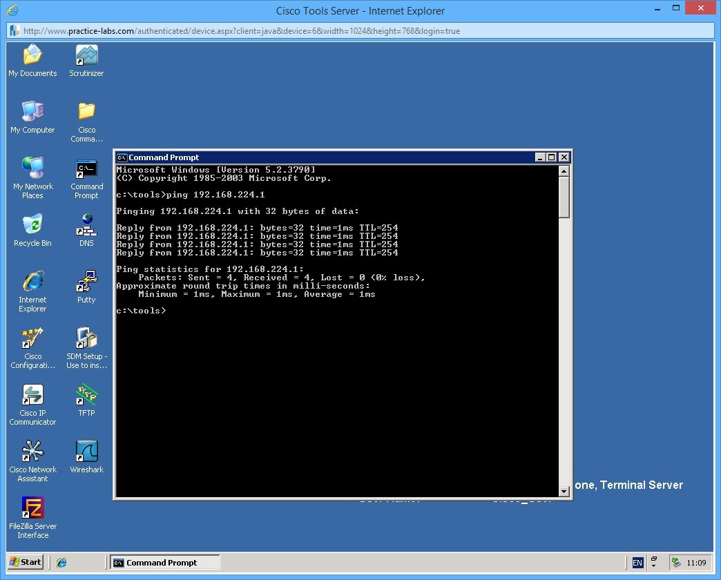
Step 5
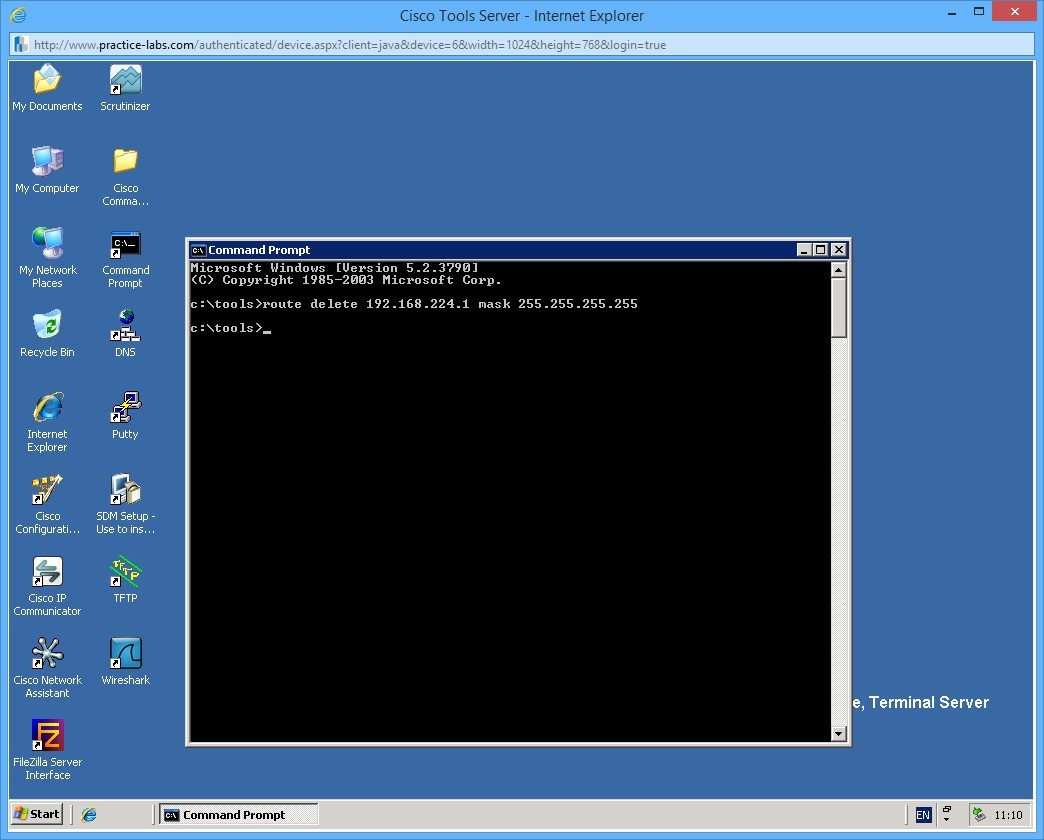
To delete a route you need to use the route delete command. On the server, use the following command to delete the route you previously added.
route delete 192.168.224.1 mask 255.255.255.255
Notice that in the delete command you do not need to specify the gateway address.
Leave all the network devices powered on and proceed to the next exercise.
Exercise 4 - Dynamic Routing
In this next exercise you will learn about dynamic routing and how this can help in maintaining routing tables on device in your network. Use your course information or your favourite search engine to find information on the following topics
- Cisco dynamic routing protocols
Task 1 - Dynamic routing
In contrast to static routing, dynamic routing involves devices exchange information using a routing protocol to help build a topology of the network. There are many different routing protocols, some are industry standard and some are proprietary (notably Cisco), and the way routing protocols work can also be slightly different depending if they are distance vector or link state based (or a hybrid of the two).
In this exercise you will create a route on NYEDGE2 and use dynamic routing to send the route to NYWAN1 dynamically.
NYEDGE2 and NYWAN1 are running a routing protocol called EIGRP which is a Cisco proprietary routing protocol. We will tell EIGRP to advertise the static route that we configure to its peers under the routing protocol configuration.
Step 1
First we will add an additional static route on NYEDGE2 and confirm its existence:
NYEDGE2>enable
NYEDGE2#configure terminal
Enter configuration commands, one per line.  End with CNTL/Z.
NYEDGE2(config)#ip route 10.55.1.0 255.255.255.0 172.14.0.4
Confirm the route exists in the routers routing table using the following commands:
exit
show ip route | include 10.55.1.0
This will show you all the routes in the routing table that contain the characters 10.55.1.0.
Command output on NYEDGE2:
NYEDGE2(config)#exit
NYEDGE2#
May 27 16:31:55: %SYS-5-CONFIG_I: Configured from console by console
NYEDGE2#
NYEDGE2#show ip route | include 10.55.1.0
S       10.55.1.0 [1/0] via 172.14.0.4
Step 2
Next confirm that NYWAN1 does not currently know about this route in its routing table. Use the previous command on NYWAN1:
NYWAN1>enable
NYWAN1#show ip route | include 10.55.1.0
Output on NYWAN1:
NYWAN1#show ip route | include 10.55.1.0
NYWAN1#
As you can see, the lack of output confirms the route does not exist.
Step 3
Next you will configure NYEDGE2 to advertise this static route to its EIGRP neighbors.
To do this, follow this sequence of commands:
NYEDGE2>enable
NYEDGE2#configure terminal
Enter configuration commands, one per line.  End with CNTL/Z.
NYEDGE2(config)#router eigrp 800
NYEDGE2(config-router)#redistribute static
These commands instruct the router to send out its static routes in the EIGRP process.
Step 5
Confirm the configuration changes by viewing the routing table on NYWAN1 once again:
NYWAN1#show ip route | include 10.55.1.0
D EX     10.55.1.0/24
You can see that the routing table now has an external EIGRP route, the route is external as it is not natively learnt by the protocol, but instead it has been injected in to the routing table from an alternative routing protocol (in this case static routing). Notice that there are two numbers in square brackets next to the route. These numbers are the administrative distance of the protocol and the metric of the route.
Administrative distance is the preference of the routing protocol, running many routing protocols on a router means potentially you can receive the same routes from different protocol sources, the router therefore needs to make a decision of which one to use. The lower the number in the first part of the bracket, the more preferable.
The metric is the cost of the route if you like, for example there may be multiple routes to a subnet but one is over a 10Mbps link and the other is over a 256Kbps link. The metric determines which route (in the same routing protocol) is more preferable.
Task 2 - Redundant paths and network failure
One of the primary benefits of dynamic routing protocols is the ability to react to network failures. As you will have learnt, if a network path becomes unavailable, for example a link fails or a device fails, then a dynamic routing protocol will attempt to find an alternative path to the destination.
In the lab, NYWAN1 has two connections to a remote router where it is learning the 192.168.224.0 subnet (and a few others).
In this exercise we will see how EIGRP is able to dynamic failover from one link to another.
Step 1
First confirm the routes learnt by EIGRP on NYWAN1 as we will use one of these to confirm our re-routing:
show ip route eigrp
Output of this command on NYWAN1:
NYWAN1#show ip route eigrp
Codes: L - local, C - connected, S - static, R - RIP, M - mobile, B - BGP
       D - EIGRP, EX - EIGRP external, O - OSPF, IA - OSPF inter area
       N1 - OSPF NSSA external type 1, N2 - OSPF NSSA external type 2
       E1 - OSPF external type 1, E2 - OSPF external type 2
       i - IS-IS, su - IS-IS summary, L1 - IS-IS level-1, L2 - IS-IS level-2
       ia - IS-IS inter area, * - candidate default, U - per-user static route
       o - ODR, P - periodic downloaded static route, H - NHRP, l - LISP
       + - replicated route, % - next hop override
Gateway of last resort is not set
      10.0.0.0/8 is variably subnetted, 3 subnets, 3 masks
D EX     10.55.1.0/24
           [170/30720] via 192.168.16.3, 00:00:33, GigabitEthernet0/0
      172.88.0.0/16 is variably subnetted, 7 subnets, 3 masks
D        172.88.0.0/16 is a summary, 00:09:30, Null0
D     192.168.100.0/24
           [90/28416] via 192.168.16.6, 00:09:18, GigabitEthernet0/0
           [90/28416] via 192.168.16.5, 00:09:18, GigabitEthernet0/0
      192.168.224.0/24 is variably subnetted, 2 subnets, 2 masks
D        192.168.224.0/24
           [90/10639872] via 172.88.0.10, 00:09:26, Serial0/0/0.256
D     192.168.225.0/24
           [90/10639872] via 172.88.0.10, 00:09:26, Serial0/0/0.256
      192.168.226.0/27 is subnetted, 2 subnets
D        192.168.226.0
           [90/10639872] via 172.88.0.10, 00:09:26, Serial0/0/0.256
D        192.168.226.32
           [90/10639872] via 172.88.0.10, 00:09:26, Serial0/0/0.256
In the output on NYWAN1 you can see that the routes in the routing table are via 172.88.0.10 and an additional subnet via 192.168.16.5 / .6
Step 2
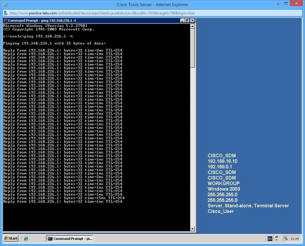
On PLABCSCO01 create a constant ping to the one of the subnets (the first host on the subnet), for example use the address 192.168.226.1 using the command:
ping 192.168.226.1 -t
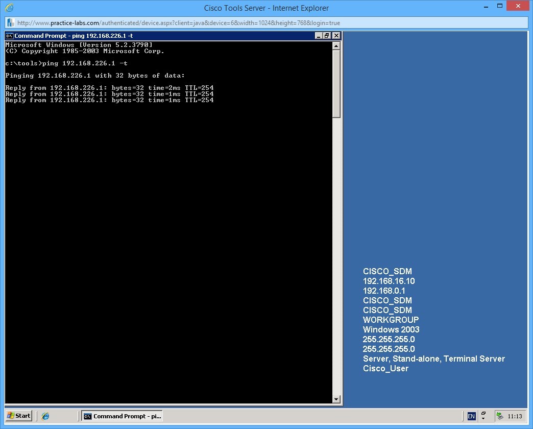
Leave the ping running for the next step.
Step 3
Next we will simulate a link failure by shutting down NYWAN1 Serial0/0/0.256 (the WAN interface) to simulate a failure.
To shut down the interface, use the following commands:
NYWAN1#configure terminal
Enter configuration commands, one per line.  End with CNTL/Z.
NYWAN1(config)#interface serial 0/0/0.256
NYWAN1(config-subif)#shutdown
NYWAN1(config-subif)#
*May 27 16:55:45: %DUAL-5-NBRCHANGE: IP-EIGRP(0) 800: Neighbor 172.88.0.10 (Serial0/0/0.256) is down: interface down
NYWAN1(config-subif)#
Quit out of the interface configuration by pressing CTRL+Z.
Above you can see a log message saying that the interface is down, and that EIGRP has lost communication to one of its neighbors.
Step 4
Switch back to the server to reconfirm your ping is still working:
Step 5
Confirm that the routing table has now changed:
NYWAN1#show ip route eigrp
Codes: L - local, C - connected, S - static, R - RIP, M - mobile, B - BGP
       D - EIGRP, EX - EIGRP external, O - OSPF, IA - OSPF inter area
       N1 - OSPF NSSA external type 1, N2 - OSPF NSSA external type 2
       E1 - OSPF external type 1, E2 - OSPF external type 2
       i - IS-IS, su - IS-IS summary, L1 - IS-IS level-1, L2 - IS-IS level-2
       ia - IS-IS inter area, * - candidate default, U - per-user static route
       o - ODR, P - periodic downloaded static route, H - NHRP, l - LISP
       + - replicated route, % - next hop override
Gateway of last resort is not set
      10.0.0.0/8 is variably subnetted, 3 subnets, 3 masks
D EX     10.55.1.0/24
           [170/30720] via 192.168.16.3, 00:02:29, GigabitEthernet0/0
      172.88.0.0/16 is variably subnetted, 6 subnets, 3 masks
D        172.88.0.0/16 is a summary, 00:00:30, Null0
D        172.88.0.8/30 [90/41024000] via 172.88.0.6, 00:00:30, Serial0/0/1.642
                       [90/41024000] via 172.88.0.2, 00:00:30, Serial0/0/0.641
D     192.168.100.0/24
           [90/28416] via 192.168.16.6, 00:11:14, GigabitEthernet0/0
           [90/28416] via 192.168.16.5, 00:11:14, GigabitEthernet0/0
      192.168.224.0/24 is variably subnetted, 2 subnets, 2 masks
D        192.168.224.0/24
           [90/40640000] via 172.88.0.6, 00:00:30, Serial0/0/1.642
           [90/40640000] via 172.88.0.2, 00:00:30, Serial0/0/0.641
D     192.168.225.0/24 [90/40640000] via 172.88.0.6, 00:00:30, Serial0/0/1.642
                       [90/40640000] via 172.88.0.2, 00:00:30, Serial0/0/0.641
      192.168.226.0/27 is subnetted, 2 subnets
D        192.168.226.0 [90/40640000] via 172.88.0.6, 00:00:30, Serial0/0/1.642
                       [90/40640000] via 172.88.0.2, 00:00:30, Serial0/0/0.641
D        192.168.226.32
           [90/40640000] via 172.88.0.6, 00:00:30, Serial0/0/1.642
           [90/40640000] via 172.88.0.2, 00:00:30, Serial0/0/0.641
You can now see that the routes in the routers routing table are via Serial 0/0/1.642 and Serial 0/0/0.641!
This is the true power of dynamic routing protocols. The different protocols achieve this functionality in different ways and in varying complexity, this is one example of how a routing protocol learns routes and can achieve failover on multiple paths. You can also achieve load-balancing too, why waste those redundant links!
You may shut down all virtual machines used in this exercise using Practice Labs power button function to revert these devices to their default settings.
Alternatively, you may sign out of the lab portal to power down all devices.
Summary
In this lab, you learned the following:
- Configure the Environment to Setup an ISATAP Router
- Setup Communication among IPv4 and IPv6 Networks
- Static Routing
- Dynamic Routing