Southern New Hampshire University | SNHU-CYB210: Computer Networking
Configure Switching Features
Exercises
- Introduction
- Lab Topology
- Exercise 1 - Trunk Configuration Part 1
- Exercise 2 - VLAN Trunk Protocol
- Exercise 3 - Trunk Configuration Part 2
- Exercise 4 - Native VLAN Configuration
- Exercise 5 - Adding and Removing VLANs from a Trunk
- Exercise 6 - Configuring EtherChannel
- Review
Introduction
Welcome to the Configure Switching Features Practice Lab. In this module, you will be provided with the instructions and devices needed to develop your hands-on skills.
Getting Started
If this is your first time using Practice Labs, please watch our Getting Started video below.
a6a3a709-99c5-4bac-874b-320d1d5c4a6f
Learning Outcomes
In this module, you will complete the following exercises:
- Exercise 1 - Trunk Configuration Part 1
- Exercise 2 - VLAN Trunk Protocol
- Exercise 3 - Trunk Configuration Part 2
- Exercise 4 - Native VLAN Configuration
- Exercise 5 - Adding and Removing VLANs from a Trunk
- Exercise 6 - Configuring EtherChannel
After completing this lab, you will be able to:
- Create a trunk link and pass two VLANs through it
- Configure DTP functions
- Configure VTP to distribute VLAN database information from one switch to another
- Identify Native VLANs, their uses, and vulnerabilities
- Configure Native VLANs for secure connectivity
- Add and remove VLANs to a trunk
- Examine and configure layer 2 and layer 3 static etherchannel
Note: Our main focus is to cover the practical, hands-on aspects of the exam objectives. We recommend referring to course material or a search engine to research theoretical topics in more detail.
Lab Duration
It will take approximately 1 hour to complete this lab.
Help and Support
For more information on using Practice Labs, please see our Help and Support page. You can also raise a technical support ticket from this page.
Click Next to view the Lab topology used in this module.
Copyright © Practice Labs 2007 - 2018. All rights reserved.
Lab Topology
During your session, you will have access to the following lab configuration.
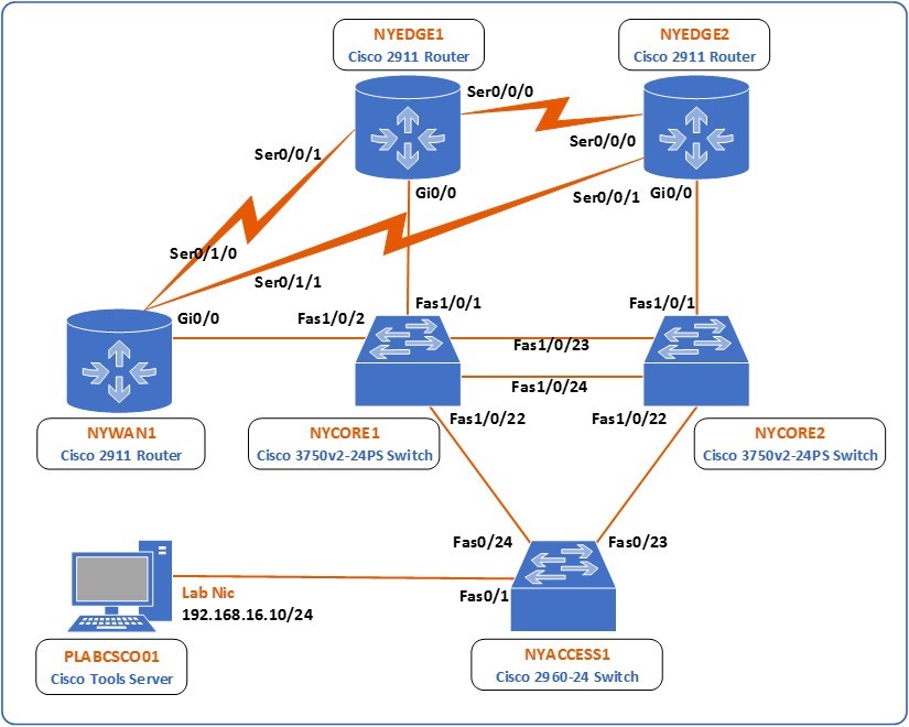 Figure 1.0 Cisco lab diagram showing the network topology used in this task: This diagram shows all of the devices in the lab, 3 switches, NYCORE1, NYCORE2 and NYACCESS1 and 3 routers NYEDGE1, NYEDGE2 and NYWAN1. The switches are connected together in a ring, with NYCORE1 and NYCORE2 being connected together with two links. The three routers are also connected in a ring via their serial interfaces. NYWAN1 also has three additional connections, two are connected to a frame-relay cloud which connects in turn to LDNWAN1, the last connection on this router is to NWRKWAN1 via NYWAN1’s gigabit ethernet 0/1 interface. Finally there is a Cisco IP phone connected to NYCORE2 Fast ethernet 1/0/12.
Depending on the exercises you may or may not use all of the devices, but they are shown here in the layout to get an overall understanding of the topology of the lab.
- NYEDGE1 (Cisco 2911 Router)
- NYEDGE2 (Cisco 2911 Router)
- NYCORE1 (Cisco 3750v2-24PS Switch)
- NYCORE2 (Cisco 3750v2-24PS Switch)
- NYACCESS1 (Cisco 2960-24 Switch)
- NYWAN1 (Cisco 2911 Router)
- PLABCSCO01 (Cisco Tools Server)
Click Next to proceed to the first exercise.
Exercise 1 - Trunk Configuration Part 1
A trunk is a link, usually between two switches, that transmits frames belonging to two or more VLANs. It is because of trunks that you are able to distribute multiple VLANs throughout multiple switches.
Learning Outcomes
After completing this exercise, you will be able to:
- Create a trunk link and pass two VLANs through it
- Configure DTP functions
Your Devices
You will be using the following devices in this lab. Please make sure these are powered on before proceeding.
- NYCORE1 (Cisco 3750v2-24PS Switch)
- NYACCESS1 (Cisco 2960-24 Switch)

Task 1 - Trunk Configuration and Dynamic Trunking Protocol Part 1
In this task, you will configure a trunk link between the NYCORE1 and NYACCESS1 switches to transmit multiple VLANs between them.
Step 1
Connect to the NYCORE1 switch and begin by creating two VLANs with the following characteristics:
- VLAN 10 name Management
- VLAN 20 name Sales
To do this, issue the following commands:
NYCORE1#configure terminal
Enter configuration commands, one per line.  End with CNTL/Z.
NYCORE1(config)#vlan 10
NYCORE1(config-vlan)#name Management
NYCORE1(config-vlan)#exit
NYCORE1(config)#vlan 20
NYCORE1(config-vlan)#name Sales
NYCORE1(config-vlan)#exit
NYCORE1(config)#
Step 2
Next, examine the lab diagram to determine which interface of the NYCORE1 switch connects with the NYACCESS1 switch. You will see that it is interface FastEthernet 1/0/22. Configure this interface as a trunk:
NYCORE1(config)#interface fastethernet 1/0/22
NYCORE1(config-if)#switchport mode trunk
Command rejected: An interface whose trunk encapsulation is "Auto" can not be configured to "trunk" mode.
NYCORE1(config-if)#
As can be seen from the message above, this attempt has failed. You must first configure the trunk encapsulation before configuring the interface as a trunk.
Step 3
To configure the trunk encapsulation, issue the following command. Use the ? as below to view all of the options you have for this command:
NYCORE1(config-if)#switchport trunk encapsulation ?
  dot1q      Interface uses only 802.1q trunking encapsulation when trunking
  isl        Interface uses only ISL trunking encapsulation when trunking
  negotiate  Device will negotiate trunking encapsulation with peer on
             interface
NYCORE1(config-if)#switchport trunk encapsulation dot1q
NYCORE1(config-if)#
The options for encapsulation are isl, dot1q and negotiate. You choose to use the dot1q option for encapsulation.
Note: The Inter-Switch Link or ISL protocol is a Cisco proprietary trunk encapsulation protocol. It has been overtaken by open standard IEEE 802.1q as the preferred trunk encapsulation protocol.
Step 4
Now attempt once again to configure this port as a trunk port:
NYCORE1(config-if)#switchport mode trunk
NYCORE1(config-if)#
*Mar  1 00:46:08.643: %LINEPROTO-5-UPDOWN: Line protocol on Interface FastEthernet1/0/22, changed state to down
*Mar  1 00:46:11.671: %LINEPROTO-5-UPDOWN: Line protocol on Interface FastEthernet1/0/22, changed state to up
NYCORE1(config-if)#exit
NYCORE1(config)#exit
NYCORE1#exit
The port has now been configured as a trunk port. Notice that the interface was brought down and came back up. This is because, by default, the other end of the link is connected to an interface that has DTP enabled.
Note: In order for a trunk to function, it must be configured as a trunk on both ends of the link. By default, switchport interfaces have the Dynamic Trunking Protocol or DTP function active. This means that ports will negotiate between them to successfully create either access or a trunk link depending on the configuration on each end. In this case, the NYCORE1 end is configured as a trunk, and the NYACCESS end is configured to auto negotiate with DTP, so the access link was torn down and a trunk link was negotiated. For more information on what combination of configurations on each end will result in what type of link, review your course material or use your favorite search engine to research this topic further.
Step 5
To verify this configuration, examine the trunk that you configured by issuing the following command:
NYCORE1#show interface trunk
Port        Mode             Encapsulation  Status        Native vlan
Fa1/0/22    on               802.1q         trunking      1
Port        Vlans allowed on trunk
Fa1/0/22    1-4094
Port        Vlans allowed and active in management domain
Fa1/0/22    1,10,20
Port        Vlans in spanning tree forwarding state and not pruned
Fa1/0/22    1,10,20
NYCORE1#
Notice that the port is on which means that auto-negotiation is not active, with an encapsulation protocol of 802.1q and it has a status of trunking. This information indicates that the trunk has been created successfully. Notice also the Native vlan which is 1. You will examine this later in this lab.
The above output also indicates which VLANs are transmitted over this trunk:
- The Vlans allowed on trunk indicates that the whole range of possible VLANs is allowed on this trunk. This is the default setting for newly created trunks.
- The Vlans allowed, and active in management domain shows the VLANs that currently exist on the switch and that are being transmitted over the trunk.
- The Vlans in spanning tree forwarding state and not pruned statement is beyond the scope of this lab.
Step 6
Next, you will configure the trunk so that only VLANs 10 and 20 are allowed over it. To do so, execute the following commands on the NYCORE1 switch:
NYCORE1#configure terminal
Enter configuration commands, one per line.  End with CNTL/Z.
NYCORE1(config)#interface fastethernet 1/0/22
NYCORE1(config-if)#switchport trunk allowed vlan 10,20
NYCORE1(config-if)#exit
NYCORE1(config)#exit
NYCORE1#
Note: When listing VLANs in the above command, there is no space after the “,” If you were to list more VLANs in such a command, you would type switchport trunk allowed vlan 10,20,30,40,50 without spaces after the “,”
Step 7
Verify this change with the following command:
NYCORE1#show interface trunk
Port        Mode             Encapsulation  Status        Native vlan
Fa1/0/22    on               802.1q         trunking      1
Port        Vlans allowed on trunk
Fa1/0/22    10,20
Port        Vlans allowed and active in management domain
Fa1/0/22    10,20
Port        Vlans in spanning tree forwarding state and not pruned
Fa1/0/22    10,20
NYCORE1#
Now only VLANs 10 and 20 are allowed and are active over the trunk.
Step 8
Now you will configure a trunk port with interface FastEthernet 1/0/23 on NYCORE2 as done on nycore1:
NYCORE2(config)#interface fastethernet 1/0/23
NYCORE2(config-if)#switchport trunk encapsulation dot1q
NYCORE2(config-if)#switchport mode trunk
NYCORE2(config-if)#
*Mar  1 00:46:08.643: %LINEPROTO-5-UPDOWN: Line protocol on Interface FastEthernet1/0/23, changed state to down
*Mar  1 00:46:11.671: %LINEPROTO-5-UPDOWN: Line protocol on Interface FastEthernet1/0/23, changed state to up
NYCORE2(config-if)#exit
NYCORE2(config)#exit
NYCORE2#exit
Step 9
Although you have configured the trunk on NYCORE1 and NYCORE2 and you have seen that the trunk is active, it is not yet correctly passing traffic. This is because the allowed VLANs have not been configured on the other end of the link.
Examine the lab diagram and determine which interface of the NYACCESS1 is at the other end of the trunk. You should see that this is interface FastEthernet 0/24. If you remember from previous steps, the trunk is currently functioning because it has DTP active by default.
Verify the DTP settings on this interface by issuing the following command on the NYACCESS1 switch:
NYACCESS1#show interface trunk
Port        Mode             Encapsulation  Status        Native vlan
Fa0/24      auto             802.1q         trunking      1
Port        Vlans allowed on trunk
Fa0/24      1-4094
Port        Vlans allowed and active in management domain
Fa0/24      1
Port        Vlans in spanning tree forwarding state and not pruned
Fa0/24      1
NYACCESS1#
You can see that the Mode is auto, which means DTP is functioning.
Step 10
Next, change the trunking mode on FastEthernet 0/24 to trunk. This will essentially turn off the use of DTP and will have both ends of the link explicitly configured as trunks. To do this, issue the following commands:
NYACCESS1#configure terminal
Enter configuration commands, one per line.  End with CNTL/Z.
NYACCESS1(config)#interface fastethernet 0/24
NYACCESS1(config-if)#switchport mode trunk
NYACCESS1(config-if)#exit
NYACCESS1(config)#exit
NYACCESS1#
Notice that there are no syslog messages indicating that the link went down. This is to be expected because the state of the link has not changed, just the method by which that state is achieved.
Step 11
The next step involves allowing the appropriate VLANs to traverse the trunk. Take a look at the VLANs that have been configured on the NYACCESS1 switch:
NYACCESS1#show vlan brief
VLAN Name                             Status    Ports
---- -------------------------------- --------- -------------------------------
1    default                          active    Fa0/1, Fa0/2, Fa0/3, Fa0/4
                                                Fa0/5, Fa0/6, Fa0/7, Fa0/8
                                                Fa0/9, Fa0/10, Fa0/11, Fa0/12
                                                Fa0/13, Fa0/14, Fa0/15, Fa0/16
                                                Fa0/17, Fa0/18, Fa0/19, Fa0/20
                                                Fa0/21, Fa0/22, Fa0/23, Gi0/1
                                                Gi0/2
1002 fddi-default                     act/unsup
1003 token-ring-default               act/unsup
1004 fddinet-default                  act/unsup
1005 trnet-default                    act/unsup
NYACCESS1#
You’ll notice that VLANs 10 and 20 are missing. In fact, the switch is in its default VLAN configuration.
One method of configuration would be to manually configure VLANs 10 and 20 and then allow them on the appropriate trunk. However, imagine you have a large organization with sixty or seventy VLANs and 25 switches. It would be a nightmare to configure all of those switches with all of those VLANs, not to mention the high probability of mistakes.
Another option, which you will use here is to use the VLAN Trunk Protocol or VTP. In the next section, you will configure VTP, and then you will return to complete the trunk configuration.
Leave the devices you have powered on in their current state and proceed to the next exercise.
Exercise 2 - VLAN Trunk Protocol
VTP is a protocol that functions in a client-server model. One device, in this case, NYCORE1, will be configured as the server where all VLAN configurations are made. Client devices, in this case, NYACCESS1 receive the information about the VLANs, created and automatically create them in their own VLAN databases.
Learning Outcomes
After completing this exercise, you will be able to:
- Configure VTP to distribute VLAN database information from one switch to another
Your Devices
You will be using the following devices in this lab. Please make sure these are powered on before proceeding.
- NYCORE1 (Cisco 3750v2-24PS Switch)
- NYACCESS1 (Cisco 2960-24 Switch)
Task 1 - Configuring VTP Between NYCORE1 and NYACCESS1
In this section, you will configure VTP between the NYCORE1 and NYACCESS1 switches so that VLAN information from the former will be propagated automatically to the latter.
Step 1
Connect to NYCORE1 and view the current VTP configuration with the following command. This is the default VTP configuration of a switch:
NYCORE1#show vtp status
VTP Version capable             : 1 to 3
VTP version running             : 1
VTP Domain Name                 :
VTP Pruning Mode                : Disabled
VTP Traps Generation            : Disabled
Device ID                       : 08cc.683f.2f00
Configuration last modified by 0.0.0.0 at 3-1-93 00:33:23
Local updater ID is 0.0.0.0 (no valid interface found)
Feature VLAN:
--------------
VTP Operating Mode                : Server
Maximum VLANs supported locally   : 1005
Number of existing VLANs          : 7
Configuration Revision            : 2
MD5 digest                        : 0x3A 0x3F 0xBE 0xD2 0x26 0x14 0x1C 0xFB
                                    0x78 0x64 0x76 0x38 0x71 0xFE 0xC9 0xA9
NYCORE1#
Look over the VTP configuration. To set up VTP on this switch, the following configuration will be implemented:
- VTP Version number: 3
- VTP Domain Name: vtp.practice-labs.com
- VTP operating mode: server
- VTP password: cisco
Note: VTP has three versions. It is always best to use the latest version. However, switches are always backward compatible in order to function on networks with older equipment. Version three offers compatibility with extended range VLANs, private VLANs and provides features that protect against the unwanted overwriting of the VLAN database. Other features include password encryption as well. To further research VTP versions, use your favorite search engine.
Step 2
To configure the NYCORE1 switch with the above parameters, enter the following commands:
NYCORE1#configure terminal
Enter configuration commands, one per line.  End with CNTL/Z.
NYCORE1(config)#vtp domain vtp.practice-labs.com
Changing VTP domain name from NULL to vtp.practice-labs.com
NYCORE1(config)#
*Mar  1 02:33:46.327: %SW_VLAN-6-VTP_DOMAIN_NAME_CHG: VTP domain name changed to vtp.practice-labs.com.
NYCORE1(config)#vtp mode server
Device mode already VTP Server for VLANS.
NYCORE1(config)#vtp version 3
*Mar  1 02:34:04.094: %SW_VLAN-6-OLD_CONFIG_FILE_READ: Old version 2 VLAN configuration file detected and read OK.  Version 3 files will be written in the future
NYCORE1(config)#vtp password cisco
Setting device VTP password to cisco
NYCORE1(config)#exit
NYCORE1#
As you initiate the commands, you will see various messages indicating the changes that you are making.
Note: You cannot change the VTP version to 3 unless you first create a VTP domain.
Step 3
Verify the VTP configuration once again:
NYCORE1#show vtp status
VTP Version capable             : 1 to 3
VTP version running             : 3
VTP Domain Name                 : vtp.practice-labs.com
VTP Pruning Mode                : Disabled
VTP Traps Generation            : Disabled
Device ID                       : 08cc.683f.2f00
Feature VLAN:
--------------
VTP Operating Mode                : Server
Number of existing VLANs          : 7
Number of existing extended VLANs : 0
Maximum VLANs supported locally   : 1005
Configuration Revision            : 0
Primary ID                        : 0000.0000.0000
Primary Description               :
MD5 digest                        : 0x00 0x00 0x00 0x00 0x00 0x00 0x00 0x00
                                    0x00 0x00 0x00 0x00 0x00 0x00 0x00 0x00
Feature MST:
--------------
VTP Operating Mode                : Transparent
Feature UNKNOWN:
--------------
VTP Operating Mode                : Transparent
NYCORE1#
Because you activated VTP v3, some additional features are shown in the output which is outside the scope of this lab. You can see however that the configuration that you implemented has been applied.
Step 4
Next, view the VTP configuration on the NYACCESS1 switch:
NYACCESS1#show vtp status
*Mar  1 02:41:05.085: %SYS-5-CONFIG_I: Configured from console bshow vtp status
VTP Version capable             : 1 to 3
VTP version running             : 1
VTP Domain Name                 : vtp.practice-labs.com
VTP Pruning Mode                : Disabled
VTP Traps Generation            : Disabled
Device ID                       : 2834.a2b7.7980
Configuration last modified by 0.0.0.0 at 3-1-93 00:33:23
Local updater ID is 0.0.0.0 (no valid interface found)
Feature VLAN:
--------------
VTP Operating Mode                : Server
Maximum VLANs supported locally   : 64
Number of existing VLANs          : 7
Configuration Revision            : 2
MD5 digest                        : 0xDA 0x70 0xB4 0x31 0x5F 0x34 0x24 0x7F
                                    0xEA 0xB7 0x4F 0xF0 0x6F 0x90 0x26 0x1C
NYACCESS1#
Almost everything is as expected except for the VTP Domain Name. You will notice that it has changed. When the VTP domain name of a switch is empty, it will join the first VTP domain it learns about. Because it is connected to the NYCORE1 switch with this VTP domain name, it automatically joins that domain.
Step 5
Next, configure the remaining VTP parameters to make NYACCESS1 a VTP client with the following commands:
NYACCESS1#configure terminal
Enter configuration commands, one per line.  End with CNTL/Z.
NYACCESS1(config)#vtp version 3
*Mar  1 02:48:23.289: %SW_VLAN-6-OLD_CONFIG_FILE_READ: Old version 2 VLAN configuration file detected and read OK.  Version 3 files will be written in the future
NYACCESS1(config)#vtp password cisco
Setting device VTP password to cisco
NYACCESS1(config)#vtp mode client
Setting device to VTP Client mode for VLANS.
NYACCESS1(config)#exit
NYACCESS1#
Step 6
The VTP configuration should be complete. After several seconds, the VLANs from the NYCORE1 switch will have been sent to NYACCESS1 and inserted into the VLAN database. To confirm this, view the VLANs on the NYACCESS1 switch:
NYACCESS1#show vlan brief
VLAN Name                             Status    Ports
---- -------------------------------- --------- -------------------------------
1    default                          active    Fa0/1, Fa0/2, Fa0/3, Fa0/4
                                                Fa0/5, Fa0/6, Fa0/7, Fa0/8
                                                Fa0/9, Fa0/10, Fa0/11, Fa0/12
                                                Fa0/13, Fa0/14, Fa0/15, Fa0/16
                                                Fa0/17, Fa0/18, Fa0/19, Fa0/20
                                                Fa0/21, Fa0/22, Fa0/23, Gi0/1
                                                Gi0/2
10   Management                       active
20   Sales                            active
1002 fddi-default                     act/unsup
1003 trcrf-default                    act/unsup
1004 fddinet-default                  act/unsup
1005 trbrf-default                    act/unsup
NYACCESS1#
VLANs 10 and 20 have been successfully added to the VLAN database.
Step 7
Next, you will see what happens when you create a new VLAN on a switch that is configured as a VTP client. Issue the following commands on the NYACCESS1 switch:
NYACCESS1#configure terminal
Enter configuration commands, one per line.  End with CNTL/Z.
NYACCESS1(config)#vlan 30
VTP VLAN configuration not allowed when device is in CLIENT mode.
NYACCESS1(config)#exit
NYACCESS1#
VLANs can no longer be manipulated from a VTP client. All changes must occur at the VTP server.
Step 8
Go back to the NYCORE1 switch, which is the VTP server, and attempt to add a new VLAN there:
NYCORE1#configure terminal
Enter configuration commands, one per line.  End with CNTL/Z.
NYCORE1(config)#vlan 30
VTP VLAN configuration not allowed when device is not the primary server for vlan database.
NYCORE1(config)#exit
NYCORE1#
Again, you are unable to create the VLAN. This is because VTP version 3 requires you to make the server a primary VTP server. To do so, make sure you are in privilege executive mode and issue the following command and press Enter when asked to confirm:
Alert: It may take several seconds for the command to execute so be patient.
NYCORE1#vtp primary
This system is becoming primary server for feature vlan
No conflicting VTP3 devices found.
Do you want to continue? [confirm]
NYCORE1#
*Mar  1 03:04:37.148: %SW_VLAN-4-VTP_PRIMARY_SERVER_CHG: 08cc.683f.2f00 has become the primary server for the VLAN VTP feature
NYCORE1#
Step 9
Now attempt once again to add a new VLAN. If successful, name it Test:
NYCORE1#configure terminal
Enter configuration commands, one per line.  End with CNTL/Z.
NYCORE1(config)#vlan 30
NYCORE1(config-vlan)#name Test
NYCORE1(config-vlan)#exit
NYCORE1(config)#
You have successfully created the VLAN.
Step 10
Go to the NYACCESS1 switch and see if the VLAN you created has been added to the database there:
NYACCESS1#show vlan brief
VLAN Name                             Status    Ports
---- -------------------------------- --------- -------------------------------
1    default                          active    Fa0/1, Fa0/2, Fa0/3, Fa0/4
                                                Fa0/5, Fa0/6, Fa0/7, Fa0/8
                                                Fa0/9, Fa0/10, Fa0/11, Fa0/12
                                                Fa0/13, Fa0/14, Fa0/15, Fa0/16
                                                Fa0/17, Fa0/18, Fa0/19, Fa0/20
                                                Fa0/21, Fa0/22, Fa0/23, Gi0/1
                                                Gi0/2
10   Management                       active
20   Sales                            active
30   Test                             active
1002 fddi-default                     act/unsup
1003 trcrf-default                    act/unsup
1004 fddinet-default                  act/unsup
1005 trbrf-default                    act/unsup
NYACCESS1#
The Test VLAN has been added successfully.
You have successfully configured VTP, and all of the necessary VLANs have automatically been propagated from NYCORE1 to the NYACCESS1 switch.
In the next section, you will complete the trunk configuration that you began at the beginning of this exercise.
Leave the devices you have powered on in their current state and proceed to the next exercise.
Exercise 3 - Trunk Configuration Part 2
In Exercise 1 you partially configured a trunk link between NYCORE1 and NYACCESS1. The configuration was completed on the NYCORE1 side, however, not on the NYACCESS1 side. You configured VTP in Exercise 2 so that NYCORE1 will automatically share its VLANs with NYACCESS1.
Now that NYACCESS1 has the appropriate VLANs configured, you can finish the trunk configuration.
Learning Outcomes
After completing this exercise, you will be able to:
- Create a trunk link and pass two VLANs through it
Your Devices
You will be using the following devices in this lab. Please make sure these are powered on before proceeding.
- NYEDGE1 (Cisco 2911 Router)
- NYWAN1 (Cisco 2911 Router)
- NYACCESS1 (Cisco 2960-24 Switch)
- NYCORE2 (Cisco 3750v2-24PS Switch)
- PLABCSCO01 (Cisco Tools Server)
Task 1 - Trunk Configuration and Dynamic Trunking Protocol Part 2
At the end of Exercise 1, you had successfully configured interface FastEthernet 0/24 on NYACCESS1 as a trunk.
Step 1
Connect to NYACCESS1 and configure the FastEthernet 0/24 interface to allow VLANs 10 and 20:
NYACCESS1#configure terminal
Enter configuration commands, one per line.  End with CNTL/Z.
NYACCESS1(config)#interface fastethernet 0/24
NYACCESS1(config-if)#switchport trunk allowed vlan 10,20
NYACCESS1(config-if)#exit
NYACCESS1(config)#exit
NYACCESS1#
Step 2
Take a look at the trunk interface with the following command to verify your configuration:
NYACCESS1#show interface trunk
Port        Mode             Encapsulation  Status        Native vlan
Fa0/24      on               802.1q         trunking      1
Port        Vlans allowed on trunk
Fa0/24      10,20
Port        Vlans allowed and active in management domain
Fa0/24      10,20
Port        Vlans in spanning tree forwarding state and not pruned
Fa0/24      10,20
NYACCESS1#
The VLANs have been added successfully to the trunk.
Note: When entering commands that allow VLANs on trunks, you are essentially overwriting any previously allowed VLAN configuration. The command removes any other allowed VLANs that may have been configured and allows only those in the command. In order to add allowed VLANs to an already existing list, use this format of the command: switchport trunk allowed vlan add XX where XX is the VLAN ID. Review your course material or use a search engine to research this topic further.
Step 3
In order to test to see if the trunk is successfully passing traffic, you must first configure some devices on VLANs 10 and 20 on both the NYCORE1 and the NYACCES1 switch. You will use the following devices, and you will place the ports they are connected to within the appropriate VLAN:
- NYEDGE1 VLAN10
- NYCORE2 VLAN10
- NYWAN1 VLAN 20
- PLABCSCO01 VLAN 20
First, configure the appropriate ports on NYCORE1. Looking at the lab diagram, you can see that port FastEthernet 1/0/1 connects to NYEDGE1 should be on VLAN 10 and FastEthernet 1/0/2 connects to NYWAN1 and should be on VLAN 20:
NYCORE1#configure terminal
Enter configuration commands, one per line.  End with CNTL/Z.
NYCORE1(config)#interface fastethernet 1/0/1
NYCORE1(config-if)#switchport mode access
NYCORE1(config-if)#switchport access vlan 10
NYCORE1(config-if)#exit
NYCORE1(config)#interface fastethernet 1/0/2
NYCORE1(config-if)#switchport mode access
NYCORE1(config-if)#switchport access vlan 20
NYCORE1(config-if)#exit
NYCORE1(config)#
Step 4
Next, configure the appropriate ports on NYACCESS1. Looking at the lab diagram, you can see that port FastEthernet 0/23 connects to NYCORE2 and should be on VLAN 10 and FastEthernet 0/1 connects to PLABCSCO01 should be on VLAN 20:
NYACCESS1#configure terminal
Enter configuration commands, one per line.  End with CNTL/Z.
NYACCESS1(config)#interface fastethernet 0/23
NYACCESS1(config-if)#switchport mode access
NYACCESS1(config-if)#switchport access vlan 10
NYACCESS1(config-if)#exit
NYACCESS1(config)#interface fastethernet 0/1
NYACCESS1(config-if)#switchport mode access
NYACCESS1(config-if)#switchport access vlan 20
NYACCESS1(config-if)#exit
NYACCESS1(config)#
*Mar  1 04:26:29.919: %LINEPROTO-5-UPDOWN: Line protocol on Interface Vlan1, changed state to down
Note: You may have noticed that the VLAN 1 interface has gone down on the NYACCESS switch. This is normal behavior. The VLAN 1 interface is what is known as a Switched Virtual Interface or SVI. Switches by their very nature are layer 2 devices and thus do not function with IP addresses. However, it is necessary to connect to them and manage them remotely. IP connectivity is achieved via the SVI. A prerequisite for the SVI to be in an up state is that at least one active port must be on the VLAN of the SVI. Otherwise, the SVI goes down. SVIs are used for other purposes as well, and you can use your favorite search engine to research them further.
Step 5
You are now ready to test your trunk configuration. For your convenience, the following is a list of IP addresses that each device is assigned with as well as the VLAN that you assigned to its port so that you can test connectivity using ping:
- NYEDGE1 - VLAN 10 - 192.168.16.1
- NYWAN1 - VLAN 20 - 192.168.16.2
- NYCORE2 - VLAN 10 - 192.168.16.4
- PLABCSCO01 - VLAN 20 - 192.168.16.10
Alert: Before testing make sure the PLABCSCO01 server is on.
Connect to NYEDGE1 and ping all three other devices. You should only get a response from NYCORE2 which is on the same VLAN:
NYEDGE1#ping 192.168.16.2
Type escape sequence to abort.
Sending 5, 100-byte ICMP Echos to 192.168.16.2, timeout is 2 seconds:
.....
Success rate is 0 percent (0/5)
NYEDGE1#ping 192.168.16.4
Type escape sequence to abort.
Sending 5, 100-byte ICMP Echos to 192.168.16.4, timeout is 2 seconds:
..!!!
Success rate is 60 percent (3/5), round-trip min/avg/max = 1/1/1 ms
NYEDGE1#ping 192.168.16.10
Type escape sequence to abort.
Sending 5, 100-byte ICMP Echos to 192.168.16.10, timeout is 2 seconds:
.....
Success rate is 0 percent (0/5)
NYEDGE1#
You only get a response from NYCORE2 which means that the communication can only have occurred over the trunk link between NYACCESS1 and NYCORE1.
Note: The lab topology shows that NYCORE2 has two links between it and NYCORE1. For the purposes of this lab, these two links have been shut down to ensure that there is only one path that the NYCORE2 device can take to reach NYEDGE1. You can confirm this by examining the ports on the NYCORE2 switch.
Step 6
Connect to NYWAN1 and ping all three other devices. This time, you should only get a response from PLABCSCO01 which is on the same VLAN:
NYWAN1#ping 192.168.16.1
Type escape sequence to abort.
Sending 5, 100-byte ICMP Echos to 192.168.16.1, timeout is 2 seconds:
.....
Success rate is 0 percent (0/5)
NYWAN1#ping 192.168.16.4
Type escape sequence to abort.
Sending 5, 100-byte ICMP Echos to 192.168.16.4, timeout is 2 seconds:
.....
Success rate is 0 percent (0/5)
NYWAN1#ping 192.168.16.10
Type escape sequence to abort.
Sending 5, 100-byte ICMP Echos to 192.168.16.10, timeout is 2 seconds:
.!!!!
Success rate is 80 percent (4/5), round-trip min/avg/max = 1/1/1 ms
NYWAN1#
Once again, you get a response only from PLABCSCO01 which is on the same VLAN. This communication can only have occurred over the trunk link.
You have successfully configured and verified the trunk configuration.
Leave the devices in their current states and continue on to the next exercise.
Exercise 4 - Native VLAN Configuration
Frames that are placed on a trunk are tagged with the VLAN ID that they belong to. What happens if a frame without a tag is placed on a trunk link? The answer is, the frame is placed on the Native VLAN.
Each trunk is configured with a Native VLAN. If it is not configured properly, it could be a source of network vulnerabilities that attackers can take advantage of.
Learning Outcomes
After completing this exercise, you will be able to:
- Identify Native VLANs, their uses, and vulnerabilities
- Configure Native VLANs for secure connectivity
Your Devices
You will be using the following devices in this lab. Please make sure these are powered on before proceeding.
- NYCORE1 (Cisco 3750v2-24PS Switch)
- NYACCESS1 (Cisco 2960-24 Switch)

Task 1 - Native VLAN Configuration
In this task, you will examine the default Native VLAN configuration of a trunk, and you will learn how to configure the Native VLAN on your network more securely.
Step 1
Connect to the NYCORE1 switch and examine the trunk interface once again with the following command:
NYCORE1#show interface trunk
Port        Mode             Encapsulation  Status        Native vlan
Fa1/0/22    on               802.1q         trunking      1
Fa1/0/23    auto             n-802.1q       trunking      1
Port        Vlans allowed on trunk
Fa1/0/22    10,20
Fa1/0/23    1-4094
Port        Vlans allowed and active in management domain
Fa1/0/22    10,20
Fa1/0/23    1,10,20,30
Port        Vlans in spanning tree forwarding state and not pruned
Fa1/0/22    10,20
Fa1/0/23    1,10,20,30
NYCORE1#
You can see that the native VLAN for this trunk is 1.
Note: It is considered a best practice to create a new VLAN other than the default VLAN, shut it down and use it as the Native VLAN. This will protect your network from vulnerabilities associated with the Native VLAN. For more information and to find out why use your favorite search engine to research this subject further.
Step 2
Create a new VLAN with ID 99, name it Native and shut it down.
Note: Remember that any VLANs you create in the NYCORE1 switch will automatically be created in the NYACESS1 switch.
NYCORE1#configure terminal
Enter configuration commands, one per line.  End with CNTL/Z.
NYCORE1(config)#vlan 99
NYCORE1(config-vlan)#name Native
NYCORE1(config-vlan)#shutdown
NYCORE1(config-vlan)#exit
NYCORE1(config)#
Step 3
Next, configure the trunk on interface FastEthernet 1/0/22 to use VLAN 99 as the native VLAN:
NYCORE1(config)#interface fastethernet 1/0/22
NYCORE1(config-if)#switchport trunk native vlan 99
NYCORE1(config-if)#exit
NYCORE1(config)#exit
NYCORE1#
Step 4
Verify this configuration by viewing the trunk interface information:
NYCORE1#show interface trunk
Port        Mode             Encapsulation  Status        Native vlan
Fa1/0/22    on               802.1q         trunking      99
Fa1/0/23    auto             n-802.1q       trunking      1
Port        Vlans allowed on trunk
Fa1/0/22    10,20
Fa1/0/23    1-4094
Port        Vlans allowed and active in management domain
Fa1/0/22    10,20
Fa1/0/23    1,10,20,30
Port        Vlans in spanning tree forwarding state and not pruned
Fa1/0/22    10,20
Fa1/0/23    1,10,20,30
NYCORE1#
The native VLAN has been successfully changed.
Note: It is important to note here that the trunk is currently not functioning correctly. There is what is called a Native VLAN mismatch. This is when the Native VLAN is configured differently on each end. This could be used to gain access to destination devices in a VLAN different from the VLAN that a source device is located in. This is known as VLAN hopping.
Step 5
In order to complete the configuration, you must connect to NYACCESS1 and configure the native VLAN correctly on the trunk. To do this, type these commands:
NYACCESS1#configure terminal
Enter configuration commands, one per line.  End with CNTL/Z.
NYACCESS1(config)#interface fastethernet 0/24
NYACCESS1(config-if)#switchport trunk native vlan 99
NYACCESS1(config-if)#exit
NYACCESS1(config)#exit
NYACCESS1#
Step 6
Verify that the trunk is currently using the right native VLAN:
NYACCESS1#show interface trunk
Port        Mode             Encapsulation  Status        Native vlan
Fa0/24      on               802.1q         trunking      99
Port        Vlans allowed on trunk
Fa0/24      10,20
Port        Vlans allowed and active in management domain
Fa0/24      10,20
Port        Vlans in spanning tree forwarding state and not pruned
Fa0/24      10,20
NYACCESS1#
The native VLAN has been configured successfully.
Leave the devices you have powered on in their current state and proceed to the next exercise.
Exercise 5 - Adding and Removing VLANs from a Trunk
As a network evolves, new VLANs must be created to accommodate the needs of the network. As a result, these VLANs often have to be propagated to multiple switches. Sometimes, VLANs are removed from networks or renumbered.
Learning Outcomes
After completing this exercise, you will be able to:
- Add and remove VLANs to a trunk
Your Devices
You will be using the following devices in this lab. Please make sure these are powered on before proceeding.
- NYCORE1 (Cisco 3750v2-24PS Switch)
- NYACCESS1 (Cisco 2960-24 Switch)

Task 1 - Adding and Removing VLAN Trunks
You currently have a trunk between NYCORE1 and NYACCESS1. You are required to add two more VLANs to the trunk, specifically, VLAN 30, Marketing and VLAN 40, Research to the trunk, but you must remove VLAN 20, Sales.
Step 1
Connect to NYCORE1 and create the two new VLANs that you will require. Verify that the VLANs have been created successfully:
NYCORE1#configure terminal
Enter configuration commands, one per line.  End with CNTL/Z.
NYCORE1(config)#vlan 30
NYCORE1(config-vlan)#name Marketing
NYCORE1(config-vlan)#exit
NYCORE1(config)#vlan 40
NYCORE1(config-vlan)#name Research
NYCORE1(config-vlan)#exit
NYCORE1(config)#exit
NYCORE1#show vlan brief
VLAN Name                             Status    Ports
---- -------------------------------- --------- -------------------------------
1    default                          active    Fa1/0/1, Fa1/0/2, Fa1/0/3
                                                Fa1/0/4, Fa1/0/5, Fa1/0/6
                                                Fa1/0/7, Fa1/0/8, Fa1/0/9
                                                Fa1/0/10, Fa1/0/11, Fa1/0/12
                                                Fa1/0/13, Fa1/0/14, Fa1/0/15
                                                Fa1/0/16, Fa1/0/17, Fa1/0/18
                                                Fa1/0/19, Fa1/0/20, Fa1/0/21
                                                Fa1/0/23, Fa1/0/24, Gi1/0/1
                                                Gi1/0/2
10   Management                       active
20   Sales                            active
30   Marketing                        active
40   Research                         active
99   Native                           act/lshut
1002 fddi-default                     act/unsup
1003 token-ring-default               act/unsup
1004 fddinet-default                  act/unsup
1005 trnet-default                    act/unsup
NYCORE1#
The VLANs have been created successfully. VTP should also have created these VLANs in the NYACCESS1 switch as well. Feel free to verify this at your leisure.
Step 2
Next, examine the trunk connection to refresh your memory as to which VLANs are currently allowed:
NYCORE1#show interface trunk
Port        Mode             Encapsulation  Status        Native vlan
Fa1/0/22    on               802.1q         trunking      99
Fa1/0/23    auto             n-802.1q       trunking      1
Port        Vlans allowed on trunk
Fa1/0/22    10,20
Fa1/0/23    1-4094
Port        Vlans allowed and active in management domain
Fa1/0/22    10,20
Fa1/0/23    1,10,20,30
Port        Vlans in spanning tree forwarding state and not pruned
Fa1/0/22    10,20
Fa1/0/23    1,10,20,30
NYCORE1#
VLANs 10 and 20 are currently allowed on the Fa1/0/22 trunk.
Step 3
In this step, you will examine the commands available to you for adding and removing VLANs from a trunk. Use Cisco’s context-sensitive help using the ? character as follows:
NYCORE1#configure terminal
Enter configuration commands, one per line.  End with CNTL/Z.
NYCORE1(config)#interface fastethernet 1/0/22
NYCORE1(config-if)#switchport trunk allowed vlan ?
  WORD    VLAN IDs of the allowed VLANs when this port is in trunking mode
  add     add VLANs to the current list
  all     all VLANs
  except  all VLANs except the following
  none    no VLANs
  remove  remove VLANs from the current list
Step 4
In this step, you will use the add keyword to add VLANs 30 and 40 to the trunk as follows:
Note: Remember not to include a space after the “,” when listing VLAN IDs.
NYCORE1(config-if)#switchport trunk allowed vlan add 30,40
NYCORE1(config-if)#exit
NYCORE1(config)#exit
NYCORE1#
Step 5
Verify that the addition was executed correctly by examining the trunk interface once again:
NYCORE1#show interface trunk
Port        Mode             Encapsulation  Status        Native vlan
Fa1/0/22    on               802.1q         trunking      99
Fa1/0/23    auto             n-802.1q       trunking      1
Port        Vlans allowed on trunk
Fa1/0/22    10,20,30,40
Fa1/0/23    1-4094
Port        Vlans allowed and active in management domain
Fa1/0/22    10,20,30,40
Fa1/0/23    1,10,20,30
Port        Vlans in spanning tree forwarding state and not pruned
Fa1/0/22    10,20
Fa1/0/23    1,10,20,30,40
NYCORE1#
Notice that both VLANs 30 and 40 have been successfully added to Fa1/0/22.
Step 6
Next, you will remove VLAN 20 as per the instructions. To do so, use the following commands:
NYCORE1#configure terminal
Enter configuration commands, one per line.  End with CNTL/Z.
NYCORE1(config)#interface fastethernet 1/0/22
NYCORE1(config-if)#switchport trunk allowed vlan remove 20
NYCORE1(config-if)#exit
NYCORE1(config)#exit
NYCORE1#
Step 7
Once again, verify the change by examining the trunk interface:
NYCORE1#show interface trunk
Port        Mode             Encapsulation  Status        Native vlan
Fa1/0/22    on               802.1q         trunking      99
Fa1/0/23    auto             n-802.1q       trunking      1
Port        Vlans allowed on trunk
Fa1/0/22    10,30,40
Fa1/0/23    1-4094
Port        Vlans allowed and active in management domain
Fa1/0/22    10,30,40
Fa1/0/23    1,10,20,30
Port        Vlans in spanning tree forwarding state and not pruned
Fa1/0/22    10,30,40
Fa1/0/23    1,10,20,30,40
NYCORE1#
The changes have been made successfully.
So far, you have made changes only to one end of the trunk. Keep in mind that the trunk is still functioning for VLAN 10 since it is correctly configured at both ends. No other VLAN, however, can traverse this trunk at this point in time.
Step 8
In this step, you will connect to the NYACCESS1 switch and configure the other end of the trunk. Specifically, you will add VLANs 30 and 40 and remove VLAN 20:
NYACCESS1#configure terminal
Enter configuration commands, one per line.  End with CNTL/Z.
NYACCESS1(config)#interface fastethernet 0/24
NYACCESS1(config-if)#switchport trunk allowed vlan add 30,40
NYACCESS1(config-if)#switchport trunk allowed vlan remove 20
NYACCESS1(config-if)#exit
NYACCESS1(config)#exit
NYACCESS1#
Step 9
Examine the trunk interface on NYACCESS1 to confirm the changes you made:
NYACCESS1#show interface trunk
Port        Mode             Encapsulation  Status        Native vlan
Fa0/24      on               802.1q         trunking      99
Port        Vlans allowed on trunk
Fa0/24      10,30,40
Port        Vlans allowed and active in management domain
Fa0/24      10,30,40
Port        Vlans in spanning tree forwarding state and not pruned
Fa0/24      10,30,40
NYACCESS1#
Both ends of the trunk are now configured correctly and are passing the appropriate trunks.
You have successfully removed and added VLANs to a trunk.
Leave the devices in their current states and move on to the next exercise.
Exercise 6 - Configuring EtherChannel
EtherChannel is a port link aggregation technology that enables you to bundle multiple switch interfaces together to act as a single aggregate link, increasing bandwidth with the added advantage of resiliency.
In this exercise, you will learn how to configure Layer 2 and Layer 3 static EtherChannel.
Learning Outcomes
After completing this exercise, you will be able to:
- Examine and configure layer 2 and layer 3 static etherchannel
Your Devices
You will be using the following devices in this lab. Please make sure these are powered on before proceeding.
- NYCORE1 (Cisco 3750v2-24PS Switch)
- NYCORE2 (Cisco 3750v2-24PS Switch)
Lab Diagram
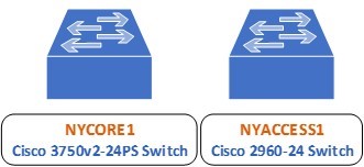
Your configurations for EtherChannel will focus on the following segment of the lab topology:
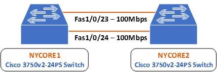
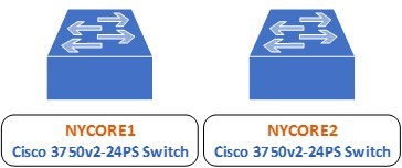
You can see that there are two physical FastEthernet connections between NYCORE1 and NYCORE2 on interfaces 1/0/23 and 1/0/24. You will create an aggregated link or an EtherChannel to bundle together these two links, so they logically appear as follows:
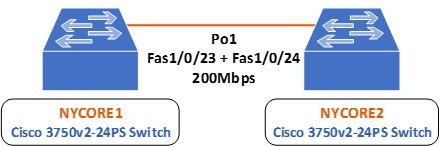
Note: The term EtherChannel and Port-Channel can be used interchangeably to refer to the bundle of aggregated links, but Port-Channel or Po is the keyword used when configuring the interface.
Task 1 - Configuring Static Layer 2 EtherChannel
Step 1
For the purposes of the previous exercises, these two links were shutdown. In this step, you will bring them back up before configuring port aggregation. To do so, connect to the command line interface of NYCORE2 and issue the following commands:
NYCORE2>enable
NYCORE2#configure terminal
NYCORE2(config)#interface range fastethernet 1/0/23 - 24
NYCORE2(config-if-range)#no shutdown
NYCORE2(config-if-range)#
*Mar  1 00:21:01.529: %LINK-3-UPDOWN: Interface FastEthernet1/0/23, changed state to up
*Mar  1 00:21:01.554: %LINK-3-UPDOWN: Interface FastEthernet1/0/24, changed state to up
*Mar  1 00:21:02.535: %LINEPROTO-5-UPDOWN: Line protocol on Interface FastEthernet1/0/23, changed state to up
*Mar  1 00:21:02.560: %LINEPROTO-5-UPDOWN: Line protocol on Interface FastEthernet1/0/24, changed state to up
NYCORE2(config-if-range)#exit
NYCORE2(config)#
Step 2
On NYCORE2, assign a channel group with an ID of 1 to each of the FastEthernet 1/0/23 and 1/0/24 interfaces. Make sure to configure a mode of on to configure the EtherChannel statically:
NYCORE2(config)#interface fastethernet 1/0/23
NYCORE2(config-if)#channel-group 1 mode on
Creating a port-channel interface Port-channel 1
NYCORE2(config-if)#exit
*Mar  1 00:06:10.214: %LINK-3-UPDOWN: Interface Port-channel1, changed state to up
*Mar  1 00:06:11.221: %LINEPROTO-5-UPDOWN: Line protocol on Interface Port-channel1, changed state to up
NYCORE2(config)#interface fastethernet 1/0/24
NYCORE2(config-if)#channel-group 1 mode on
NYCORE2(config-if)#exit
NYCORE2(config)#exit
NYCORE2#
Notice that interface Port-channel 1 changed state to up once you created it.
Step 3
Go to NYCORE1 and configure the same settings as on NYCORE2:
NYCORE1#configure terminal
Enter configuration commands, one per line.  End with CNTL/Z.
NYCORE1(config)#interface fastethernet 1/0/23
NYCORE1(config-if)#channel-group 1 mode on
Creating a port-channel interface Port-channel 1
NYCORE1(config-if)#exit
NYCORE1(config)#
*Mar  1 00:09:56.388: %LINK-3-UPDOWN: Interface Port-channel1, changed state to up
*Mar  1 00:09:57.394: %LINEPROTO-5-UPDOWN: Line protocol on Interface Port-channel1, changed state to up
NYCORE1(config)#interface fastethernet 1/0/24
NYCORE1(config-if)#channel-group 1 mode on
NYCORE1(config-if)#exit
NYCORE1(config)# exit
NYCORE1#
*Mar  1 00:10:17.326: %LINEPROTO-5-UPDOWN: Line protocol on Interface Vlan1, changed state to down
*Mar  1 00:10:19.993: %SYS-5-CONFIG_I: Configured from console by console
*Mar  1 00:10:24.414: %LINEPROTO-5-UPDOWN: Line protocol on Interface Vlan1, changed state to up
NYCORE1#
You will notice similar syslog messages here including the change of state of interface VLAN 1 as well. This is normal behavior.
Step 4
To confirm your EtherChannel is operational, use the following command on the NYCORE1 switch:
NYCORE1#show etherchannel summary
Flags:  D - down        P - bundled in port-channel
        I - stand-alone s - suspended
        H sh- Hot-standby (LACP only)
        R - Layer3      S - Layer2
        U - in use      f - failed to allocate aggregator
        M - not in use, minimum links not met
        u - unsuitable for bundling
        w - waiting to be aggregated
        d - default port
Number of channel-groups in use: 1
Number of aggregators:           1
Group  Port-channel  Protocol    Ports
------+-------------+-----------+-----------------------------------------------
1      Po1(SU)          -        Fa1/0/23(P) Fa1/0/24(P)
NYCORE1#
It appears that the EtherChannel has been created and it is operational.
Step 5
You can view further details about this EtherChannel configuration with the following command:
NYCORE1#show interfaces port-channel 1 etherchannel
Age of the Port-channel   = 0d:00h:06m:48s
Logical slot/port   = 10/1          Number of ports = 2
GC                  = 0x00000000      HotStandBy port = null
Port state          = Port-channel Ag-Inuse
Protocol            =    -
Port security       = Disabled
Ports in the Port-channel:
Index   Load   Port     EC state        No of bits
------+------+------+------------------+-----------
  0     00     Fa1/0/23 On                 0
  0     00     Fa1/0/24 On                 0
Time since last port bundled:    0d:00h:06m:38s    Fa1/0/24
Time since last port Un-bundled: 0d:00h:06m:48s    Fa1/0/24
NYCORE1#
You have successfully configured a static EtherChannel configuration.
Task 2 - Configuring Static Layer 3 EtherChannel
Once an EtherChannel Port-Channel has been created, it is possible, just like physical interfaces, to configure it as a routable port. That is, it can be configured to have an IP address and to function just like a router interface would.
In this exercise, you will configure the EtherChannel interfaces on both NYCORE1 and NYCORE2 as Layer 3 EtherChannel interfaces.
It is important to first remove the current EtherChannel configuration in order to avoid Layer2 and Layer3 configuration mismatches.
Step 1
First, you will clear all of the EtherChannel configurations that you have created until now on both NYCORE1 and NYCORE2. To do so, implement the following commands:
NYCORE1
NYCORE1#configure terminal
Enter configuration commands, one per line.  End with CNTL/Z.
NYCORE1(config)#interface range fastethernet 1/0/23 - 24
NYCORE1(config-if-range)#no channel-group 1
NYCORE1(config-if-range)#exit
NYCORE1(config)#no interface port-channel 1
NYCORE1(config)#exit
NYCORE1#
NYCORE2
NYCORE2#configure terminal
Enter configuration commands, one per line.  End with CNTL/Z.
NYCORE2(config)#interface range fastethernet 1/0/23 - 24
NYCORE2(config-if-range)#no channel-group 1
NYCORE2(config-if-range)#exit
NYCORE2(config)#no interface port-channel 1
NYCORE2(config)#exit
NYCORE2#
You will see a series of syslog messages indicating that the interfaces have gone down.
Step 2
On NYCORE1, configure both the FastEthernet 1/0/23 and 1/0/24 interfaces as routed interfaces and assign them to channel-group 1 with a mode of on:
NYCORE1#configure terminal
Enter configuration commands, one per line.  End with CNTL/Z.
NYCORE1(config)#interface range fastethernet 1/0/23 - 24
NYCORE1(config-if-range)#no switchport
NYCORE1(config-if-range)#channel-group 1 mode on
Creating a port-channel interface Port-channel 1
NYCORE1(config-if-range)#
NYCORE1(config-if-range)#exit
NYCORE1(config)#
Although they are not shown above, a syslog message will indicate that ports are going down and coming back up. The most important syslog message should be the one indicating that the port-channel 1 has come up.
Step 3
You have made the physical interfaces routed ports. This means the new port-channel 1 interface is also a routed port. Here you will assign an IP address of 192.168.18.1/24 to this routed port:
A routed port by definition is one that can have an IP address assigned to it. This is also called a Layer3 port. If assigning an IP address is successful, then the EtherChannel created is indeed Layer3.
NYCORE1(config)#interface port-channel 1
NYCORE1(config-if)#ip address 192.168.18.1 255.255.255.0
NYCORE1(config-if)#exit
NYCORE1(config)#
The assignment of the IP address is successful.
Step 4
Similarly, configure the other end of the Etherchannel connection on NYCORE2 with the following commands. Assign an address of 192.168.18.2/24 on this interface:
NYCORE2#configure terminal
Enter configuration commands, one per line.  End with CNTL/Z.
NYCORE2(config)#interface range fastethernet 1/0/23 - 24
NYCORE2(config-if-range)#no switchport
NYCORE2(config-if-range)#channel-group 1 mode on
Creating a port-channel interface Port-channel 1
NYCORE2(config-if-range)#exit
NYCORE2(config)#interface port-channel 1
NYCORE2(config-if)#ip address 192.168.18.2 255.255.255.0
NYCORE2(config-if)#exit
NYCORE2(config)#exit
NYCORE2#
Syslog messages are generated once again but are omitted from the above output.
Step 5
Test the connectivity between the two ends of the EtherChannel link by pinging NYCORE1 from NYCORE2:
NYCORE2#ping 192.168.18.1
Type escape sequence to abort.
Sending 5, 100-byte ICMP Echos to 192.168.18.1, timeout is 2 seconds:
.!!!!
Success rate is 80 percent (4/5), round-trip min/avg/max = 1/4/8 ms
NYCORE2#
The ping is successful.
Step 6
Examine the EtherChannel summary on NYCORE2:
NYCORE2#show etherchannel summary
Flags:  D - down        P - bundled in port-channel
        I - stand-alone s - suspended
        H - Hot-standby (LACP only)
        R - Layer3      S - Layer2
        U - in use      f - failed to allocate aggregator
        M - not in use, minimum links not met
        u - unsuitable for bundling
        w - waiting to be aggregated
        d - default port
Number of channel-groups in use: 1
Number of aggregators:           1
Group  Port-channel  Protocol    Ports
------+-------------+-----------+-----------------------------------------------
1      Po1(RU)          -        Fa1/0/23(P) Fa1/0/24(P)
NYCORE2#
In the Port-channel column, notice the flags (RU). R indicates a routed or Layer3 EtherChannel and U indicates that the port-channel is up.
You have successfully configured a Layer3 EtherChannel link.
Keep all devices that you have powered on in their current state and proceed to the next exercise.
Review
Well done, you have completed the Configure Switching Features Practice Lab.
Summary
You completed the following exercises:
- Exercise 1 - Trunk Configuration Part 1
- Exercise 2 - VLAN Trunk Protocol
- Exercise 3 - Trunk Configuration Part 2
- Exercise 4 - Native VLAN Configuration
- Exercise 5 - Adding and Removing VLANs from a Trunk
- Exercise 6 - Configuring EtherChannel
You should now be able to:
- Create a trunk link and pass two VLANs through it
- Configure DTP functions
- Configure VTP to distribute VLAN database information from one switch to another
- Identify Native VLANs, their uses, and vulnerabilities
- Configure Native VLANs for secure connectivity
- Add and remove VLANs to a trunk
- Examine and configure layer 2 and layer 3 static etherchannel
Shutdown all virtual machines used in this lab. Alternatively, you can log out of the lab platform.