Southern New Hampshire University | SNHU-CYB210: Computer Networking
Routing Concepts and Protocols
Exercises
- Introduction
- Lab Topology
- Exercise 1 - Static Routing
- Exercise 2 - Dynamic Routing
- Exercise 3 - Static and Dynamic Routing
- Exercise 4 - Floating Static Route
- Exercise 5 - Configuring Multiple Dynamic Routing Protocols
- Review
Introduction
Welcome to the Routing Concepts and Protocols Practice Lab. In this module, you will be provided with the instructions and devices needed to develop your hands-on skills.
dc640c20-9434-45ea-b7c2-6d4d6a196bfc
Learning Outcomes
In this module, you will complete the following exercises:
- Exercise 1 - Static Routing
- Exercise 2 - Dynamic Routing
- Exercise 3 - Static and Dynamic Routing
- Exercise 4 - Floating Static Route
- Exercise 5 - Configuring Multiple Dynamic Routing Protocols
After completing this lab, you will be able to:
- Implement static routing
- Use RIP to implement dynamic routing
- Compare static and dynamic routing
- Implement a floating static route
- Configure multiple dynamic routing protocols on the same network
Note: Our main focus is to cover the practical, hands-on aspects of the exam objectives. We recommend referring to course material or a search engine to research theoretical topics in more detail.
Lab Duration
It will take approximately 1 hour to complete this lab.
Help and Support
For more information on using Practice Labs, please see our Help and Support page. You can also raise a technical support ticket from this page.
Click Next to view the Lab topology used in this module.
Copyright © Practice Labs 2007 - 2018. All rights reserved.
Lab Topology
During your session, you will have access to the following lab configuration.
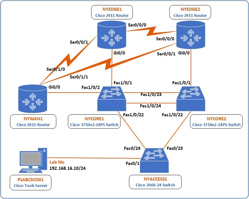 Figure 1.0 Cisco lab diagram is showing the network topology used in this task: This diagram shows all of the devices in the lab, 3 switches, NYCORE1, NYCORE2 and NYACCESS1 and 3 routers NYEDGE1, NYEDGE2, and NYWAN1. The switches are connected together in a ring, with NYCORE1 and NYCORE2 being connected together with two links. The three routers are also connected in a ring via their serial interfaces. NYWAN1 also has three additional connections; two are connected to a frame-relay cloud which connects in turn to LDNWAN1, the last connection on this router is to NWRKWAN1 via NYWAN1’s gigabit ethernet 0/1 interface. Finally, there is a Cisco IP phone connected to NYCORE2 Fast ethernet 1/0/12.
Depending on the exercises you may or may not use all of the devices, but they are shown here in the layout to get an overall understanding of the topology of the lab.
- NYEDGE1 (Cisco 2911 Router)
- NYEDGE2 (Cisco 2911 Router)
- NYCORE1 (Cisco 3750v2-24PS Switch)
- NYCORE2 (Cisco 3750v2-24PS Switch)
- NYACCESS1 (Cisco 2960-24 Switch)
- NYWAN1 (Cisco 2911 Router)
- PLABCSCO01 (Cisco Tools Server)
Click Next to proceed to the first exercise.
Exercise 1 - Static Routing
In this exercise, you will learn how to view and understand a routing table and how to configure static routes and verify their configuration.
Learning Outcomes
After completing this exercise, you will be able to:
Your Devices
You will be using the following devices in this lab. Please make sure these are powered on before proceeding.
- NYEDGE1 (Cisco 2911 Router)
- NYEDGE2 (Cisco 2911 Router)
- NYWAN1 (Cisco 2911 Router)

Task 1 - Viewing the Routing Table
A routing table on a router is a list of networks that are known to that device. The routing table includes information such as how to reach each network and how far away each network is. If a network is unknown, then a special address called a default gateway or a default route is used. Traffic with a destination that is unknown to the device will be sent to the default gateway.
Note: When speaking about end devices such as a PC or a server, this special address is known as a default gateway. In the context of a network device such as a router, this special address is known as a default route or gateway of last resort.
In this section, you will view the routing table that exists on the NYEDGE1 router and understand the information it displays.
Step 1
Connect to the NYEDGE1 router and issue the following command:
NYEDGE1#show ip route
Codes: L - local, C - connected, S - static, R - RIP, M - mobile, B - BGP
       D - EIGRP, EX - EIGRP external, O - OSPF, IA - OSPF inter area
       N1 - OSPF NSSA external type 1, N2 - OSPF NSSA external type 2
       E1 - OSPF external type 1, E2 - OSPF external type 2
       i - IS-IS, su - IS-IS summary, L1 - IS-IS level-1, L2 - IS-IS level-2
       ia - IS-IS inter area, * - candidate default, U - per-user static route
       o - ODR, P - periodic downloaded static route, H - NHRP, l - LISP
       + - replicated route, % - next hop override
Gateway of last resort is not set
      192.168.16.0/24 is variably subnetted, 2 subnets, 2 masks
C        192.168.16.0/24 is directly connected, GigabitEthernet0/0
L        192.168.16.1/32 is directly connected, GigabitEthernet0/0
NYEDGE1#
This command displays the routing table of the device. The output is separated into several sections:
- Codes - This is a legend for the codes found at the beginning of each line of the routing table. The codes are used to indicate how a specific route has been learned.
- Gateway of last resort is not set - This indicates that the default route has not been configured. If it had been, it would appear here.
- The routing table itself - The routing table consists of entries of networks. These are further explained below:
Step 2
Examine the following line of the routing table:
C 192.168.16.0/24 is directly connected, GigabitEthernet0/0
From the above entry, you can determine the following:
The network 192.168.16.0/24 is a known network since it exists in the routing table. This network is directly connected to an interface of the router. This can be seen by the C code at the beginning of the line but also because it indicates the interface to which the network is connected, specifically GigabitEthernet 0/0.
Note: A directly connected network is one whose network address contains the IP address of an interface of the router. In the case of NYEDGE1, the interface GigabitEthernet 0/0 has an IP address of 192.168.16.1 and a subnet mask of 255.255.255.0. Therefore, the network to which the specific interface is connected to is 192.168.0.0/24. The router actually inserts this route in the routing table directly from the information contained in the configuration of the interfaces.
Starting from IOS version 15 and onward, an additional routing entry is added for each directly connected route. This entry has a code of L and is known as a local or host route. This is nothing more than the IP address of the interface which is associated with the directly connected route with a subnet /32 subnet mask indicating a host. An example of this can be seen in the following route entry:
L 192.168.16.1/32 is directly connected, GigabitEthernet0/0
You can see from the above that a router that has no routing configuration implemented has only its directly connected networks as entries in the routing table, that is, those with codes C and L.
Step 3
In this step, you will configure the GigabitEthernet 0/1 interface of the NYEDGE1 router with an IP address of 172.14.0.1 and a subnet mask of 255.255.255.0, and you will activate it. You will then examine what affect this has on the routing table. To do this, issue the following commands:
NYEDGE1#configure terminal
Enter configuration commands, one per line.  End with CNTL/Z.
NYEDGE1(config)#interface gigabitethernet 0/1
NYEDGE1(config-if)#ip address 172.14.0.1 255.255.255.0
NYEDGE1(config-if)#no shutdown
NYEDGE1(config-if)#exit
NYEDGE1(config)#exit
NYEDGE1#
Note: Make sure to include the no shutdown command. If you configure the IP address and you don’t bring the interface up, the routing table will not include the new routing entries. A directly connected routing entry will only be added if the interface associated with the IP address is active.
Step 4
Examine the routing table once again:
NYEDGE1#show ip route
Codes: L - local, C - connected, S - static, R - RIP, M - mobile, B - BGP
       D - EIGRP, EX - EIGRP external, O - OSPF, IA - OSPF inter area
       N1 - OSPF NSSA external type 1, N2 - OSPF NSSA external type 2
       E1 - OSPF external type 1, E2 - OSPF external type 2
       i - IS-IS, su - IS-IS summary, L1 - IS-IS level-1, L2 - IS-IS level-2
       ia - IS-IS inter area, * - candidate default, U - per-user static route
       o - ODR, P - periodic downloaded static route, H - NHRP, l - LISP
       + - replicated route, % - next hop override
Gateway of last resort is not set
      172.14.0.0/16 is variably subnetted, 2 subnets, 2 masks
C        172.14.0.0/24 is directly connected, GigabitEthernet0/1
L        172.14.0.1/32 is directly connected, GigabitEthernet0/1
      192.168.16.0/24 is variably subnetted, 2 subnets, 2 masks
C        192.168.16.0/24 is directly connected, GigabitEthernet0/0
L        192.168.16.1/32 is directly connected, GigabitEthernet0/0
NYEDGE1#
Notice that additional entries appear in the routing table. Compare those new entries with the IP address that was configured on interface GigabitEthernet 0/1 in the previous step.
Task 2 - Implementing Static Routes
As you have seen so far, if no static or dynamic routing is configured on a router, the only routes in the routing table are those of the directly connected networks.
In this section, you will add a static route to the NYWAN1 router that will allow the NYEDGE1 router reach the 172.16.16.0/24 network. Specifically, you will add a static route so that the NYEDGE1 will be able to ping the GigabitEthernet 0/1 interface of the NYWAN1 router. Take a look at the lab topology once again to visualize your goal more clearly.
Step 1
Examine the routing table of the NYEDGE1 router once again. You can use the following command to omit the code legend from the output:
NYEDGE1#show ip route | begin Gateway
Gateway of last resort is not set
      172.14.0.0/16 is variably subnetted, 2 subnets, 2 masks
C        172.14.0.0/24 is directly connected, GigabitEthernet0/1
L        172.14.0.1/32 is directly connected, GigabitEthernet0/1
      192.168.16.0/24 is variably subnetted, 2 subnets, 2 masks
C        192.168.16.0/24 is directly connected, GigabitEthernet0/0
L        192.168.16.1/32 is directly connected, GigabitEthernet0/0
NYEDGE1#
The text after the | begin section of the command is case sensitive.
You will notice that the 172.16.16.0/24, which is the subnet you want to reach, is not included in the routing table. So any attempts to reach it will fail. You can confirm this by attempting to ping the IP address of the GigabitEthernet 0/1 interface of the NYWAN1 router which has an IP address of 172.16.16.1:
NYEDGE1#ping 172.16.16.11
Type escape sequence to abort.
Sending 5, 100-byte ICMP Echos to 172.16.16.1, timeout is 2 seconds:
.....
Success rate is 0 percent (0/5)
NYEDGE1#
Step 2
Before you add a static route that will enable NYEDGE1 to reach the desired network, you must first determine where NYEDGE1 must send any packets that are destined for the 172.16.16.0/24 network. Examining the lab topology, you can see that such packets should be sent to the GigabitEthernet 0/0 interface of NYWAN1. Connect to the NYWAN1 router to determine the IP address of this interface:
NYWAN1#show ip interface brief
Interface                  IP-Address      OK? Method Status                Protocol
Embedded-Service-Engine0/0 unassigned      YES unset  administratively down down
GigabitEthernet0/0         192.168.16.3    YES manual administratively down down
GigabitEthernet0/1         172.16.16.1     YES manual administratively down down
GigabitEthernet0/2         unassigned      YES unset  administratively down down
Serial0/0/0                unassigned      YES unset  administratively down down
Serial0/0/1                unassigned      YES unset  administratively down down
Serial0/1/0                unassigned      YES unset  administratively down down
Serial0/1/1                unassigned      YES unset  administratively down down
Serial0/2/0                unassigned      YES unset  administratively down down
NYWAN1#
The IP address of the GigabitEthernet 0/0 interface is 192.168.16.3. For the static route that you will create, this will be the next hop address.
Step 3
Return to NYEDGE1 and configure the static route. As you enter the command, use the context-sensitive help using the ? character as seen below to aid you in appropriately issuing the command:
NYEDGE1#configure terminal
Enter configuration commands, one per line.  End with CNTL/Z.
NYEDGE1(config)#ip route ?
  A.B.C.D  Destination prefix
  profile  Enable IP routing table profile
  static   Allow static routes
  vrf      Configure static route for a VPN Routing/Forwarding instance
NYEDGE1(config)#ip route 172.16.16.0 ?
  A.B.C.D  Destination prefix mask
NYEDGE1(config)#ip route 172.16.16.0 255.255.255.0 ?
  A.B.C.D                  Forwarding router's address
  Async                    Async interface
  Auto-Template            Auto-Template interface
!<-- Output Omitted -->
NYEDGE1(config)#ip route 172.16.16.0 255.255.255.0 192.168.16.3
NYEDGE1(config)#exit
NYEDGE1#
Step 4
Examine the routing table of the NYEDGE1 router once again:
NYEDGE1#show ip route | begin Gateway
Gateway of last resort is not set
      172.14.0.0/16 is variably subnetted, 2 subnets, 2 masks
C        172.14.0.0/24 is directly connected, GigabitEthernet0/1
L        172.14.0.1/32 is directly connected, GigabitEthernet0/1
      172.16.0.0/24 is subnetted, 1 subnets
S        172.16.16.0 [1/0] via 192.168.16.3
      192.168.16.0/24 is variably subnetted, 2 subnets, 2 masks
C        192.168.16.0/24 is directly connected, GigabitEthernet0/0
L        192.168.16.1/32 is directly connected, GigabitEthernet0/0
NYEDGE1#
Notice a new routing entry with a code of S has been added. It states that to reach 172.16.16.0, you must go via 192.168.16.3 which is the GigabitEthernet 0/0 interface of the NYWAN1 router.
Step 5
You will now test the route by attempting to reach the 172.16.16.0/24 subnet. You will attempt once again to ping the IP address of the GigabitEthernet 0/1 interface of the NYWAN1 router which has an IP address of 172.16.16.1:
NYEDGE1#ping 172.16.16.1
Type escape sequence to abort.
Sending 5, 100-byte ICMP Echos to 172.16.16.1, timeout is 2 seconds:
.!!!!
Success rate is 80 percent (4/5), round-trip min/avg/max = 1/1/1 ms
NYEDGE1#
The ping should be successful.
Note: When pinging from a Cisco device, the “.” indicates the ping request has timed out. The “!” indicates a successful reply. You will notice that occasionally, the first several pings have timed out. It may be that even the first 5 pings time out and you may need to issue the command again. This is normal, as the first time such a communication is made between devices, an interval of time is necessary to successfully execute an Address Resolution Protocol or ARP request. If you still don’t have replies to your pings after two tries, review your configuration. To find out more about the ARP protocol, its purpose and how it works, use your favorite search engine to research the subject further.
Step 6
Configure one more static route, this time to the 172.14.0.0/24 network from the NYWAN1 router. Review the lab topology to orientate yourself and understand the purpose of this static route. The next hop IP address will be 192.168.16.1 which is the IP address of the GigabitEthernet 0/0 interface on the NYEDGE1 router. Connect to the NYWAN1 router and issue the following commands:
NYWAN1#configure terminal
Enter configuration commands, one per line.  End with CNTL/Z.
NYWAN1(config)#ip route 172.14.0.0 255.255.255.0 192.168.16.1
NYWAN1(config)#exit
NYWAN1#
Step 7
Test the results of this command by attempting to ping 172.14.0.1 which is the IP address of the GigabitEtherent 0/1 interface of the NYEDGE1 router:
NYWAN1#ping 172.14.0.1
Type escape sequence to abort.
Sending 5, 100-byte ICMP Echos to 172.14.0.1, timeout is 2 seconds:
!!!!!
Success rate is 100 percent (5/5), round-trip min/avg/max = 1/1/4 ms
NYWAN1#
The ping should be successful.
At this point, you have successfully implemented two static routes on the NYEDGE1 and NYWAN1 routers.
Task 3 - Implementing a Default Route
As mentioned before, a default route is a special type of static route that routes all packets destined for networks that are not specifically included in the routing table.
In this exercise, you will configure a default route on the NYEDGE1 router.
Step 1
Examine the routing table of the NYEDGE1 router once again:
NYEDGE1#show ip route | begin Gateway
Gateway of last resort is not set
      172.14.0.0/16 is variably subnetted, 2 subnets, 2 masks
C        172.14.0.0/24 is directly connected, GigabitEthernet0/1
L        172.14.0.1/32 is directly connected, GigabitEthernet0/1
      172.16.0.0/24 is subnetted, 1 subnets
S        172.16.16.0 [1/0] via 192.168.16.3
      192.168.16.0/24 is variably subnetted, 2 subnets, 2 masks
C        192.168.16.0/24 is directly connected, GigabitEthernet0/0
L        192.168.16.1/32 is directly connected, GigabitEthernet0/0
NYEDGE1#
Notice the Gateway of last resort is not set message. This means that the default route has not been configured.
Step 2
To configure the default route, you must determine the next hop IP address for the static route. The default route should route packets to the Internet. Looking at the lab topology, the path to the Internet from NYEDGE1 is via the ISP1 router. The IP address of this router is 172.14.0.3, so this will be the next hop IP that you will configure. Implement the following commands to configure the default route:
NYEDGE1#configure terminal
Enter configuration commands, one per line.  End with CNTL/Z.
NYEDGE1(config)#ip route 0.0.0.0 0.0.0.0 172.14.0.3
NYEDGE1(config)#exit
NYEDGE1#
The 0.0.0.0 0.0.0.0 address subnet mask pair indicate “anything”. So, all IP addresses that don’t match any other more specific route will match this one. This is what is required since any destination that is not matched in the routing table should be matched by the default route.
Step 3
Examine the routing table of the NYEDGE1 router once again. This time do not include the | begin Gateway modifier:
NYEDGE1#show ip route
Codes: L - local, C - connected, S - static, R - RIP, M - mobile, B - BGP
       D - EIGRP, EX - EIGRP external, O - OSPF, IA - OSPF inter area
       N1 - OSPF NSSA external type 1, N2 - OSPF NSSA external type 2
       E1 - OSPF external type 1, E2 - OSPF external type 2
       i - IS-IS, su - IS-IS summary, L1 - IS-IS level-1, L2 - IS-IS level-2
       ia - IS-IS inter area, * - candidate default, U - per-user static route
       o - ODR, P - periodic downloaded static route, H - NHRP, l - LISP
       + - replicated route, % - next hop override
Gateway of last resort is 172.14.0.3 to network 0.0.0.0
S*    0.0.0.0/0 [1/0] via 172.14.0.3
      172.14.0.0/16 is variably subnetted, 2 subnets, 2 masks
C        172.14.0.0/24 is directly connected, GigabitEthernet0/1
L        172.14.0.1/32 is directly connected, GigabitEthernet0/1
      172.16.0.0/24 is subnetted, 1 subnets
S        172.16.16.0 [1/0] via 192.168.16.3
      192.168.16.0/24 is variably subnetted, 2 subnets, 2 masks
C        192.168.16.0/24 is directly connected, GigabitEthernet0/0
L        192.168.16.1/32 is directly connected, GigabitEthernet0/0
NYEDGE1#
First, notice that a new static route with a code of S* has been added. You know that S means static, but looking at the codes, you can see that the * indicates a candidate default. This means that this could become the default route.
Looking at the line just above this static route, you see the text Gateway of last resort is 172.14.0.3 to network 0.0.0.0. This means that this static route has indeed become the default route.
Leave all the network devices powered on and proceed to the next exercise.
Exercise 2 - Dynamic Routing
In this exercise, you will learn how to implement dynamic routing. In contrast to static routing, dynamic routing involves the exchange of routing information between devices using a routing protocol. From this information, each device builds a topology of the network. There are many different routing protocols, some are industry standard, and some are proprietary. These routing protocols fall into two major categories depending on how they function. These categories are distance vector and link state.
Learning Outcomes
After completing this exercise, you will be able to:
- Use RIP to implement dynamic routing
Your Devices
You will be using the following devices in this lab. Please make sure these are powered on before proceeding.
- NYEDGE1 (Cisco 2911 Router)
- NYEDGE2 (Cisco 2911 Router)
- NYWAN1 (Cisco 2911 Router)

Task 1 - Configuring Routing Information Protocol
In this task, you will configure Routing Information Protocol (RIP) which is a distance vector routing protocol.
Step 1
Before making any routing configurations on the routers, you will first activate a loopback interface that has been preconfigured on the NYEDGE1 router. This loopback interface will simulate a subnet that will be advertised by RIP.
Think of a looback interface as a virtual router interface. It is essentially just like any other router interface except that it has no physical counterpart. It has many purposes in the real world. However, its purpose for this lab is to allow for additional networks to exist on the router without the need for additional physical ports. For more information, use your favorite search engine to search for loopback interfaces.
The loopback 0 interface has an IP address of 172.18.0.1/24 and thus is in the 172.18.0.0/24 subnet.
Issue the following commands to activate the loopback 0 interface:
NYEDGE1#configure terminal
Enter configuration commands, one per line.  End with CNTL/Z.
NYEDGE1(config)#interface loopback 0
NYEDGE1(config-if)#no shutdown
NYEDGE1(config-if)#exit
Sep 11 23:59:23.339: %LINK-3-UPDOWN: Interface Loopback0, changed state to up
Sep 11 23:59:24.339: %LINEPROTO-5-UPDOWN: Line protocol on Interface Loopback0, changed state to up
NYEDGE1(config)#
Step 2
Next, you will enable the RIP protocol with the following command:
NYEDGE1(config)#router rip
NYEDGE1(config-router)#
RIP has now been enabled on the NYEDGE1 router. Notice how the prompt changes to NYEDGE1(config-router)#. This is because you are now in the configuration mode in which you can configure all of the RIP parameters of the router.
Step 3
At this point, RIP is enabled, however, no routes are being advertised to other RIP routers. You must indicate to the router which directly connected networks will participate in the RIP process. To do this, you can use the network command as follows:
NYEDGE1(config-router)#network 172.14.0.0
NYEDGE1(config-router)#network 192.168.16.0
NYEDGE1(config-router)#network 172.18.0.0
NYEDGE1(config-router)#exit
NYEDGE1(config)#exit
NYEDGE1#
Remember to include the 172.18.0.0 network which belongs to the loopback 0 interface.
The router has now begun advertising these three networks out of all its active interfaces. Notice that these are the networks to which the two active physical interfaces and the looback interface of the router are directly connected.
When adding networks with the network command, these must be directly connected networks. It is possible to add any network using this command as you will not get an error message, however, a network command that contains a network other than the directly connected networks will have no effect on any configuration.
By advertising these networks, the router is essentially saying that any other router that wants to get to these network destinations should send their packets to it. At this point, however, there is no other router configured to listen to such advertisements.
Step 4
In this step, you will configure the RIP protocol on the NYEDGE2 router as follows:
NYEDGE2#configure terminal
Enter configuration commands, one per line.  End with CNTL/Z.
NYEDGE2(config)#router rip
NYEDGE2(config-router)#
Step 5
Just as before, RIP is enabled, but no routes are being advertised. Indicate which directly connected networks will participate in the RIP process, again, by using the network command as follows:
NYEDGE2(config-router)#network 172.14.0.0
NYEDGE2(config-router)#network 192.168.16.0
NYEDGE2(config-router)#exit
NYEDGE2(config)#exit
NYEDGE2#
Notice once again that these are the networks to which the two active interfaces of the router are directly connected.
Step 6
Now take a look at the routing table of NYEDGE2:
NYEDGE2#show ip route | begin Gateway
Gateway of last resort is not set
      172.14.0.0/16 is variably subnetted, 2 subnets, 2 masks
C        172.14.0.0/24 is directly connected, GigabitEthernet0/1
L        172.14.0.2/32 is directly connected, GigabitEthernet0/1
R     172.18.0.0/16 [120/1] via 192.168.16.1, 00:00:01, GigabitEthernet0/0
                    [120/1] via 172.14.0.1, 00:00:07, GigabitEthernet0/1
      192.168.16.0/24 is variably subnetted, 2 subnets, 2 masks
C        192.168.16.0/24 is directly connected, GigabitEthernet0/0
L        192.168.16.2/32 is directly connected, GigabitEthernet0/0
NYEDGE2#
A new entry in the routing table appears with the R code indicating that the route was learned via the RIP protocol. The destination network is that of the loopback 0 interface on NYEDGE1. You will also note that in order to reach this new network of 172.18.0.0, there are two possible routes: one via the 192.168.16.1 next hop and one via 172.14.0.1. These are the GigabitEthernet 0/0 and 0/1 interfaces of NYEDGE1 router respectively. Both options are equally viable routes to reach the desired network.
In general, when using dynamic routing protocols, when multiple routes are available to a specific network destination, only the best route is included in the routing table. The only exception is when the routes are of both equal cost and equal administrative distance as is the case in this example. In this instance, both routes will be used to reach this destination. This has benefits because you can now have redundant paths to your destination and you can load balance the traffic between these routes as well. You will find out more about these concepts in later lab modules, or you can use your favorite search engine to research them further.
Step 7
Test to make sure that this new route that was added is functioning correctly. Attempt to ping the loopback 0 interface of the NYEDGE1 router from the NYEDGE2 router and examine the results:
NYEDGE2#ping 172.18.0.1
Type escape sequence to abort.
Sending 5, 100-byte ICMP Echos to 172.18.0.1, timeout is 2 seconds:
!!!!!
Success rate is 100 percent (5/5), round-trip min/avg/max = 1/1/4 ms
NYEDGE2#
The ping should be successful.
You have successfully configured dynamic routing between the NYEDGE1 and NYEDGE2 routers.
Leave the devices in their current states and continue on to the next exercise.
Exercise 3 - Static and Dynamic Routing
There are many advantages to dynamic routing as compared to static routing. The major advantage is the way that dynamic routing automatically adjusts to changes in the network whereas static routing requires manual changes to the configuration in order to accommodate such changes.
Learning Outcomes
After completing this exercise, you will be able to:
- Compare static and dynamic routing
Your Devices
You will be using the following devices in this lab. Please make sure these are powered on before proceeding.
- NYEDGE1 (Cisco 2911 Router)
- NYEDGE2 (Cisco 2911 Router)
- NYWAN1 (Cisco 2911 Router)

Task 1 - Compare Static and Dynamic Routing
In the previous two exercises, you configured a static route on NYEDGE1 to the 172.16.16.0/24 network, a static route on NYWAN1 to the 172.14.0.0/24 network and you configured dynamic routing between NYEDGE1 and NYEDGE2. In this exercise, you will see how these configurations are affected by changes in the network.
Step 1
First, you will test connectivity to the GigabitEthernet 0/1 interface of the NYEDGE1 router from both the NYWAN1 router and the NYEDGE2 router. The first test will use the static route you configured while the second test will use the dynamic routing you implemented. Connect to the NYWAN1 router and issue the following command:
NYWAN1#ping 172.14.0.1
Type escape sequence to abort.
Sending 5, 100-byte ICMP Echos to 172.14.0.1, timeout is 2 seconds:
!!!!!
Success rate is 100 percent (5/5), round-trip min/avg/max = 1/1/4 ms
NYWAN1#
Connect to the NYEDGE2 router and attempt the same command:
NYEDGE2#ping 172.14.0.1
Type escape sequence to abort.
Sending 5, 100-byte ICMP Echos to 172.14.0.1, timeout is 2 seconds:
!!!!!
Success rate is 100 percent (5/5), round-trip min/avg/max = 1/1/4 ms
NYEDGE2#
Connectivity is successful in both cases.
Step 2
In this step, you will implement a change to the network. Specifically, you will change the IP address of the GigabitEthernet 0/1 interface of the NYEDGE1 router from 172.14.0.1/24 to 172.15.0.1/24 as this will place this interface in a completely new subnet. You will then add this new network to the RIP advertised networks. Connect to the NYEDGE1 router and issue the following commands:
NYEDGE1#configure terminal
Enter configuration commands, one per line.  End with CNTL/Z.
NYEDGE1(config)#interface GigabitEthernet 0/1
NYEDGE1(config-if)#ip address 172.15.0.1 255.255.255.0
NYEDGE1(config-if)#exit
NYEDGE1(config)#router rip
NYEDGE1(config-router)#network 172.15.0.0
NYEDGE1(config-router)#exit
NYEDGE1(config)#
Step 3
Next, you will attempt to reach this new IP address from both the NYWAN1 and the NYEDGE2 routers:
NYWAN1#ping 172.15.0.1
Type escape sequence to abort.
Sending 5, 100-byte ICMP Echos to 172.14.1.1, timeout is 2 seconds:
.....
Success rate is 0 percent (0/5)
NYWAN1#
As expected, the attempt from NYWAN1 has failed.
NYEDGE2#ping 172.15.0.1
Type escape sequence to abort.
Sending 5, 100-byte ICMP Echos to 172.15.0.1, timeout is 2 seconds:
!!!!!
Success rate is 100 percent (5/5), round-trip min/avg/max = 1/1/4 ms
NYEDGE2#
The attempt from NYEDGE2, however, is successful.
Step 4
Examine the routing table of NYEDGE2:
NYEDGE2#show ip route | begin Gateway
Gateway of last resort is not set
      172.14.0.0/16 is variably subnetted, 2 subnets, 2 masks
C        172.14.0.0/24 is directly connected, GigabitEthernet0/1
L        172.14.0.2/32 is directly connected, GigabitEthernet0/1
R     172.15.0.0/16 [120/1] via 192.168.16.1, 00:00:19, GigabitEthernet0/0
R     172.18.0.0/16 [120/1] via 192.168.16.1, 00:00:19, GigabitEthernet0/0
      192.168.16.0/24 is variably subnetted, 2 subnets, 2 masks
C        192.168.16.0/24 is directly connected, GigabitEthernet0/0
L        192.168.16.2/32 is directly connected, GigabitEthernet0/0
NYEDGE2#
You should notice two things. First of all, a new route entry has been added with a destination of 172.15.0.0 via 192.168.16.1. This is to be expected as this is the new network that was added to NYEDGE1 and advertised via RIP.
The second thing is a little more subtle. The routing entry of 172.18.0.0 now has only one possible route whereas before, there were two. This is because the second or redundant route was via 172.14.0.1 which was the IP address of the GigabitEthernet 0/1 interface of NYEDGE1. You have now changed the IP address of this interface and thus belongs to a different subnet. Therefore this route is no longer available. Notice that this information was exchanged between the two routers automatically via the RIP routing protocol.
Step 5
Unlike the automatically updated routes in NYEDGE2, in order to successfully route from NYWAN1 to the new IP address on NYEDGE1, you must manually reconfigure the static route on NYWAN1. To do this, connect to NYWAN1. You will first remove the static route that you had configured in a previous exercise by issuing the following command:
NYWAN1(config)#no ip route 172.14.0.0 255.255.255.0 192.168.16.1
NYWAN1(config)#
You will then implement the new static route:
NYWAN1(config)#ip route 172.15.0.0 255.255.255.0 192.168.16.1
NYWAN1(config)#exit
NYWAN1#
Step 6
Finally, you will test to see if this new static route is configured correctly by pinging the new IP address of the interface on NYEDGE1:
NYWAN1#ping 172.15.0.1
Type escape sequence to abort.
Sending 5, 100-byte ICMP Echos to 172.15.0.1, timeout is 2 seconds:
!!!!!
Success rate is 100 percent (5/5), round-trip min/avg/max = 1/1/1 ms
NYWAN1#
The ping is successful.
Note: The network that you configured in this lab involved three routers. You might be able to successfully administrate a network of this size with static routing. However, imagine configuring routing in a network that has ten or twenty routers. If you configured static routing, you would have to configure each router separately. This would not only be time-consuming, but it would also require long periods of network downtime. Such a configuration would also be prone to errors and would require extensive troubleshooting. Dynamic routing protocols, on the other hand, allow you to make a change to the network in one location without having to change anything else on any other device. The changes are propagated throughout the network quickly, automatically and accurately.
Leave the devices in their current states and continue on to the next exercise.
Exercise 4 - Floating Static Route
A floating static route is a static route that the router uses to back up a dynamic route. You must configure a floating static route with a higher administrative distance than the dynamic route that it backs up. In this way, the router prefers a dynamic route to a floating static route. The floating static route will be automatically used as a replacement if the dynamic route is lost.
Note: Administrative distance is a feature that routers use in order to select the best path when there are two or more different routes to the same destination from two different routing protocols or sources. Use your favorite search engine to research this topic further.
Learning Outcomes
After completing this exercise, you will be able to:
- Implement a floating static route
Your Devices
You will be using the following devices in this lab. Please make sure these are powered on before proceeding.
- NYEDGE1 (Cisco 2911 Router)
- NYEDGE2 (Cisco 2911 Router)
- NYWAN1 (Cisco 2911 Router)

Task 1 - Configure a Floating Static Route
In this task, you will configure a floating static route on the NYEDGE1 router.
Step 1
Before you implement the floating static route, you will first have to reconfigure the IP address of the GigabitEthernet 0/1 interface of NYEDGE1 that you changed in a previous exercise. To do so, issue the following commands:
NYEDGE1#configure terminal
Enter configuration commands, one per line.  End with CNTL/Z.
NYEDGE1(config)#interface GigabitEthernet 0/1
NYEDGE1(config-if)#ip address 172.14.0.1 255.255.255.0
NYEDGE1(config-if)#exit
NYEDGE1(config)#exit
NYEDGE1#
Step 1
Examine the routing table of NYEDGE2:
NYEDGE2#show ip route | begin Gateway
Gateway of last resort is not set
      172.14.0.0/16 is variably subnetted, 2 subnets, 2 masks
C        172.14.0.0/24 is directly connected, GigabitEthernet0/1
L        172.14.0.2/32 is directly connected, GigabitEthernet0/1
R     172.15.0.0/16 [120/1] via 192.168.16.1, 00:00:19, GigabitEthernet0/0
R     172.18.0.0/16 [120/1] via 192.168.16.1, 00:00:19, GigabitEthernet0/0
      192.168.16.0/24 is variably subnetted, 2 subnets, 2 masks
C        192.168.16.0/24 is directly connected, GigabitEthernet0/0
L        192.168.16.2/32 is directly connected, GigabitEthernet0/0
NYEDGE2#
Note: If “172.15.0.0/16“does not appear, please execute the commands from Exercise 3, Task 1, Step 2 again on NYEDGE1.
There are two dynamically learned routes in this routing table. You will create a floating static route to back up the route to the 172.18.0.0 network. Remember that this network is on a loopback interface on NYEDGE1.
Step 2
To implement the floating static route, you will first have to determine the alternate path that will be configured. Looking at the lab diagram, let’s assume that an alternate route to 172.18.0.0 exists via 172.14.0.1 which is the IP of the GigabitEthernet 0/1 interface of NYEDGE1.
Note that this IP address has been changed in a previous exercise. For the purposes of this lab, however, let us suppose that it has not been changed. You will not test connectivity to this interface in any case.
Step 3
Next, determine the administrative distance or AD of the route you want to back up. Examine the following line which is an excerpt of the routing table of NYEDGE2:
R 172.18.0.0/16 [120/1] via 192.168.16.1, 00:00:19, GigabitEthernet0/0
The first of the two numbers in the square brackets [ ] is the AD. Here the AD has a value of 120, so the AD that you will configure for the floating static route must be higher. You can use a value of 130 in your configuration.
Step 4
Now you can configure the floating static route. The route will have the following characteristics:
- Route to 172.18.0.0/24
- Next hop router 172.14.0.1
- Administrative distance 130
To implement the floating static route, issue the following commands on NYEDGE2:
NYEDGE2#configure terminal
Enter configuration commands, one per line.  End with CNTL/Z.
NYEDGE2(config)#ip route 172.18.0.0 255.255.255.0 172.14.0.1 130
NYEDGE2(config)#exit
NYEDGE2#
Step 5
Examine the routing table of NYEDGE2 once again:
Gateway of last resort is not set
      172.14.0.0/16 is variably subnetted, 2 subnets, 2 masks
C        172.14.0.0/24 is directly connected, GigabitEthernet0/1
L        172.14.0.2/32 is directly connected, GigabitEthernet0/1
R     172.15.0.0/16 [120/1] via 192.168.16.1, 00:00:05, GigabitEthernet0/0
      172.18.0.0/16 is variably subnetted, 2 subnets, 2 masks
R        172.18.0.0/16 [120/1] via 192.168.16.1, 00:00:05, GigabitEthernet0/0
S        172.18.0.0/24 [130/0] via 172.14.0.1
      192.168.16.0/24 is variably subnetted, 2 subnets, 2 masks
C        192.168.16.0/24 is directly connected, GigabitEthernet0/0
L        192.168.16.2/32 is directly connected, GigabitEthernet0/0
NYEDGE2#
Notice that the static route has been added to the routing table. There is no special designation for a floating static route in a routing table. It just backs up the dynamic route that is already in the table.
You have successfully configured a floating static route.
Leave the devices in their current states and continue on to the next exercise.
Exercise 5 - Configuring Multiple Dynamic Routing Protocols
It is possible to configure a network with multiple routing protocols. Depending on how they are configured different destinations can be advertised and learned using different routing protocols. Some destinations can be advertised by multiple routing protocols, and the router chooses, based on specific criteria, which information will be used to populate its routing table.
In this exercise, you will create additional subnets on loopback interfaces on the NYEDGE1 router, and you will advertise these subnets using OSPF and EIGRP.
Learning Outcomes
After completing this exercise, you will be able to:
- Configure multiple dynamic routing protocols on the same network
Your Devices
You will be using the following devices in this lab. Please make sure these are powered on before proceeding.
- NYEDGE1 (Cisco 2911 Router)
- NYEDGE2 (Cisco 2911 Router)
- NYWAN1 (Cisco 2911 Router)
Task 1 - Configuring the Open Shortest Path First Routing Protocol
In this section, you will implement dynamic routing such that NYEDGE1 and NYEDGE2 will dynamically exchange routing information using the Open Shortest Path First (OSPF) routing protocol.
Step 1
In this step, you will create a new loopback interface on NYEDGE1 whose subnet will be advertised via OSPF. You will create the loopback 1 interface with an IP address of 172.19.0.1/24, and thus it will be in the 172.19.0.0/24 subnet.
Issue the following commands on the NYEDGE1 router to create and configure the loopback 1 interface with the appropriate IP address:
NYEDGE1#configure terminal
Enter configuration commands, one per line.  End with CNTL/Z.
NYEDGE1(config)#interface loopback 1
NYEDGE1(config-if)#ip address 172.19.0.1 255.255.255.0
NYEDGE1(config-if)#exit
Sep 11 23:59:23.339: %LINK-3-UPDOWN: Interface Loopback1, changed state to up
Sep 11 23:59:24.339: %LINEPROTO-5-UPDOWN: Line protocol on Interface Loopback1, changed state to up
NYEDGE1(config)#
Note: Unlike physical interfaces on a router, the loopback interfaces, once created, are enabled by default, so the no shutdown command is unnecessary.
Step 2
Next, you will enable the OSPF protocol. As you enter the command, use the context-sensitive help using the ? character as seen below to aid you in understanding the command’s parameters:
NYEDGE1(config)#router ospf ?
  <1-65535>  Process ID
NYEDGE1(config)#router ospf 1
NYEDGE1(config-router)#
Notice that OSPF asks for a process ID. This is because, unlike RIP, it is possible to run multiple instances of OSPF on a single router. In this example, use a process ID of 1.
Once again, just like RIP, the prompt changes to NYEDGE1(config-router)# and you are now in the configuration mode in which you can configure all of the OSPF parameters of the router.
Step 3
At this point, OSPF is enabled, however, no routes are being advertised to other OSPF routers. You must indicate to the router which directly connected networks will participate in the OSPF process. To do this, you can use the network command. Issue the following command to advertise all of the directly connected subnets including the subnet of the loopback 1 interface, that is, the 172.19.0.0 subnet:
NYEDGE1(config-router)#network 172.14.0.0 0.0.0.255 area 0
NYEDGE1(config-router)#network 192.168.16.0 0.0.0.255 area 0
NYEDGE1(config-router)#network 172.19.0.0 0.0.0.255 area 0
NYEDGE1(config-router)#exit
NYEDGE1(config)#exit
NYEDGE1#
There are several things to notice in the above commands:
- If you remember in the previous section, other than the network on loopback 1, you already advertised these networks using RIP. It is possible to advertise the same network using multiple routing protocols. You will see the results in the following steps.
- Unlike RIP, OSPF requires a wildcard mask, in this case, 0.0.0.255. This is because it is a classful routing protocol and requires that information in order to function successfully.
- OSPF functions with the concept of areas. This makes the protocol scalable for large enterprises where OSPF routing can be segmented into multiple areas. All implementations of OSPF must have at least one area 0 defined in order for the protocol to function correctly. If there is only one area, as is the case here, the area must be defined as area 0.
Note: To find out more about wildcard masks and the defining of OSPF areas, review your course study material or use your favorite search engine to research these topics further.
The router has now begun advertising these networks out of all its active interfaces. Again, the router is sending information to all other OSPF-enabled routers to which it is connected that any packets destined for this specific subnet can be sent to it. At this point, however, there is no other router configured to listen to such advertisements. You will remedy that in the next step.
Step 4
You will now configure the OSPF protocol on the NYEDGE2 router as follows:
NYEDGE2#configure terminal
Enter configuration commands, one per line.  End with CNTL/Z.
NYEDGE2(config)#router ospf 1
NYEDGE2(config-router)#
Note: Note that the process ID does not necessarily have to be the same across all routers participating in OSPF. It is only locally significant.
Step 5
OSPF is enabled, but no routes are being advertised. Indicate which directly connected networks will participate in the OSPF process, again, by using the network command. Specifically, you will advertise the 172.14.0.0 network using OSPF:
NYEDGE2(config-router)#network 172.14.0.0 0.0.0.255 area 0
NYEDGE2(config-router)#exit
NYEDGE2(config)#exit
NYEDGE2#
*Sep  2 14:34:47: %OSPF-5-ADJCHG: Process 1, Nbr 172.19.0.1 on GigabitEthernet0/1 from LOADING to FULL, Loading Done
Another difference that OSPF has from RIP is the fact that it creates and maintains neighbor relationships or adjacencies with its OSPF neighbors. In the above output, you should see a syslog message indicating that a new adjacency has been created. You should also see something similar show up on the command line interface of the NYEDGE1 router.
Step 6
In this step you will examine the neighbor adjacency that has been created with the following command on the NYEDGE2 router:
NYEDGE2#show ip ospf neighbor
Neighbor ID     Pri   State           Dead Time   Address         Interface
172.19.0.1        1   FULL/BDR        00:00:36    172.14.0.1      GigabitEthernet0/1
NYEDGE2#
From the above output you can determine the following:
- The Neighbor ID is an IP address of the NYEDGE1 router, so it is indeed an OSPF neighbor
- The state is FULL which means that the required exchange of OSPF packets has been completed and the adjacency is nominal
- The dead time is a timer that counts down until the next exchange of packets between the neighbors keeps the adjacency alive. If the dead timer goes to zero, the adjacency is terminated
- The Address and the Interface are those of the local router, that is NYEDGE2, via which the adjacency has been created
Step 7
Now take a look at the routing table of NYEDGE2:
NYEDGE2#show ip route | begin Gateway
Gateway of last resort is not set
      172.14.0.0/16 is variably subnetted, 2 subnets, 2 masks
C        172.14.0.0/24 is directly connected, GigabitEthernet0/1
L        172.14.0.2/32 is directly connected, GigabitEthernet0/1
      172.18.0.0/16 is variably subnetted, 2 subnets, 2 masks
R        172.18.0.0/16 [120/1] via 192.168.16.1, 00:00:21, GigabitEthernet0/0
                       [120/1] via 172.14.0.1, 00:00:13, GigabitEthernet0/1
S        172.18.0.0/24 [130/0] via 172.14.0.1
      172.19.0.0/32 is subnetted, 1 subnets
O        172.19.0.1 [110/2] via 172.14.0.1, 00:11:50, GigabitEthernet0/1
      192.168.16.0/24 is variably subnetted, 2 subnets, 2 masks
C        192.168.16.0/24 is directly connected, GigabitEthernet0/0
L        192.168.16.2/32 is directly connected, GigabitEthernet0/0
NYEDGE2#
Here you will notice that the new loopback interface network is included as an OSPF route while the RIP route is still in the routing table. Both OSPF and RIP can coexist on the same network.
Task 2 - Configuring the Enhanced Interior Gateway Routing Protocol
In this section, you will implement dynamic routing such that NYEDGE1 and NYEDGE2 will dynamically exchange routing information using the Enhanced Interior Gateway Routing Protocol (EIGRP).
Step 1
In this step, you will create a new loopback interface on NYEDGE1 whose subnet will be advertised via EIGRP. You will create the loopback 2 interface with an IP address of 172.20.0.1/24, and thus it will be in the 172.20.0.0/24 subnet.
Issue the following commands on the NYEDGE1 router to create and configure the loopback 1 interface with the appropriate IP address:
NYEDGE1#configure terminal
Enter configuration commands, one per line.  End with CNTL/Z.
NYEDGE1(config)#interface loopback 2
NYEDGE1(config-if)#ip address 172.20.0.1 255.255.255.0
NYEDGE1(config-if)#exit
Sep 11 23:59:23.339: %LINK-3-UPDOWN: Interface Loopback2, changed state to up
Sep 11 23:59:24.339: %LINEPROTO-5-UPDOWN: Line protocol on Interface Loopback2, changed state to up
NYEDGE1(config)#
Step 2
Next, you will enable the EIGRP protocol. As you enter the command, use the context-sensitive help using the ? character as seen below to aid you in understanding the command’s parameters:
NYEDGE1(config)#router eigrp ?
  <1-65535>  Autonomous System
  WORD       EIGRP Virtual-Instance Name
NYEDGE1(config)#router eigrp 1
NYEDGE1(config-router)#
Notice that EIGRP asks for an Autonomous System Number. Unlike the process ID of OSPF, this number must be the same across all EIGRP routers participating in dynamic routing. In this example, use an Autonomous System Number of 1.
Once again, just like RIP and OSPF, the prompt changes to NYEDGE1(config-router)# and you are now in the configuration mode in which you can configure all of the EIGRP parameters of the router.
Step 3
At this point, EIGRP is enabled, however, no routes are being advertised to other EIGRP routers. You must indicate to the router which directly connected networks will participate in the EIGRP process. To do this, you can use the network command. Issue the following command to advertise all of the directly connected subnets including the subnet of the loopback 2 interface, that is, the 172.20.0.0 subnet:
NYEDGE1(config-router)#network 172.14.0.0 0.0.0.255
NYEDGE1(config-router)#network 192.168.16.0 0.0.0.255
NYEDGE1(config-router)#network 172.20.0.0 0.0.0.255
NYEDGE1(config-router)#exit
NYEDGE1(config)#exit
NYEDGE1#
There are several things to notice in the above commands:
- Just like OSPF, EIGRP requires a wildcard mask, in this case, 0.0.0.255. This is because it too is a classful routing protocol and requires that information in order to function successfully.
- Unlike OSPF, EIGRP does not require the defining of an area. EIGRP uses the concept Autonomous Systems (AS) instead
The router has now begun advertising these networks via EIGRP out of all its active interfaces. Again, the router is sending information to all other EIGRP-enabled routers to which it is connected that any packets destined for this specific subnet can be sent to it. At this point, however, there is no other router configured to listen to such advertisements. You will remedy that in the next step.
Step 4
You will now configure the EIGRP protocol on the NYEDGE2 router as follows:
NYEDGE2#configure terminal
Enter configuration commands, one per line.  End with CNTL/Z.
NYEDGE2(config)#router eigrp 1
NYEDGE2(config-router)#
Note that the AS number of 1 must be the same across all routers participating in EIGRP.
Step 5
Just as before, EIGRP is enabled, but no routes are being advertised. Indicate which directly connected networks will participate in the EIGRP process, again, by using the network command. Specifically, you will advertise the 172.14.0.0 network using EIGRP:
NYEDGE2(config-router)#network 172.14.0.0 0.0.0.255
NYEDGE2(config-router)#exit
NYEDGE2(config)#exit
NYEDGE2#
*Sep  2 15:05:32: %DUAL-5-NBRCHANGE: EIGRP-IPv4 1: Neighbor 172.14.0.1 (GigabitEthernet0/1) is up: new adjacency
Just like OSPF, EIGRP creates neighbor adjacencies. In the above output, you should see a syslog message indicating that a new adjacency has been created. You should also see something similar show up on the command line interface of the NYEDGE1 router.
Step 6
In this step you will examine the neighbor adjacency that has been created with the following command on the NYEDGE2 router:
NYEDGE2#show ip eigrp neighbors
EIGRP-IPv4 Neighbors for AS(1)
H   Address                 Interface              Hold Uptime   SRTT   RTO  Q  Seq
                                                   (sec)         (ms)       Cnt Num
0   172.14.0.1              Gi0/1                    14 00:01:14    3   100  0  2
NYEDGE2#
From the above output you can determine the following:
- The Neighbor ID is an IP address of the NYEDGE1 router, so it is indeed an EIGRP neighbor
- The interface in which the adjacency exists is the GigabitEthernet 0/1 interface, indeed the interface via which the NYEDGE1 router is connected
- The Uptime is the amount of time that the neighbor adjacency is active
Step 7
Now take a look at the routing table of NYEDGE2:
NYEDGE2#show ip route | begin Gateway
Gateway of last resort is not set
      172.14.0.0/16 is variably subnetted, 2 subnets, 2 masks
C        172.14.0.0/24 is directly connected, GigabitEthernet0/1
L        172.14.0.2/32 is directly connected, GigabitEthernet0/1
      172.18.0.0/16 is variably subnetted, 2 subnets, 2 masks
R        172.18.0.0/16 [120/1] via 192.168.16.1, 00:00:09, GigabitEthernet0/0
                       [120/1] via 172.14.0.1, 00:00:17, GigabitEthernet0/1
S        172.18.0.0/24 [130/0] via 172.14.0.1
      172.19.0.0/32 is subnetted, 1 subnets
O        172.19.0.1 [110/2] via 172.14.0.1, 00:07:07, GigabitEthernet0/1
      172.20.0.0/24 is subnetted, 1 subnets
D        172.20.0.0 [90/156160] via 172.14.0.1, 00:00:06, GigabitEthernet0/1
      192.168.16.0/24 is variably subnetted, 2 subnets, 2 masks
C        192.168.16.0/24 is directly connected, GigabitEthernet0/0
L        192.168.16.2/32 is directly connected, GigabitEthernet0/0
Here you will notice that an additional EIGRP route has been added indicated by the “D” in the left-hand column. The routes to the other loopback interface networks that were learned via OSPF and the RIP are still in the routing table. All three routing protocols can coexist on the same network.
You have successfully configured dynamic routing between the NYEDGE1 and NYEDGE2 routers.
a0c7f7e9-da6e-4252-83fc-38e7690f9e72
Keep all devices that you have powered on in their current state and proceed to the next exercise.
Review
Well done, you have completed the Routing Concepts and Protocols Practice Lab.
Summary
You completed the following exercises:
- Exercise 1 - Static Routing
- Exercise 2 - Dynamic Routing
- Exercise 3 - Static and Dynamic Routing
- Exercise 4 - Floating Static Route
- Exercise 5 - Configuring Multiple Dynamic Routing Protocols
You should now be able to:
- Implement static routing
- Use RIP to implement dynamic routing
- Compare static and dynamic routing
- Implement a floating static route
- Configure multiple dynamic routing protocols on the same network
Shutdown all virtual machines used in this lab. Alternatively, you can log out of the lab platform.